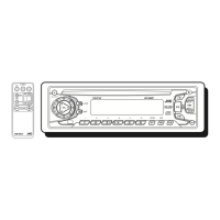
KS-FX230
1-3
Disassembly method
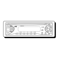
1. Disengage the four tabs in the right and left side of
unit and pull the front chassis forward to remove it.
Removing the front chassis (see Fig.1)
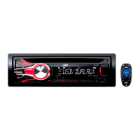
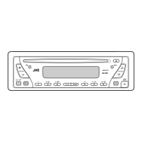
Removing the bottom cover and heat
sink (see Fig.2,3)
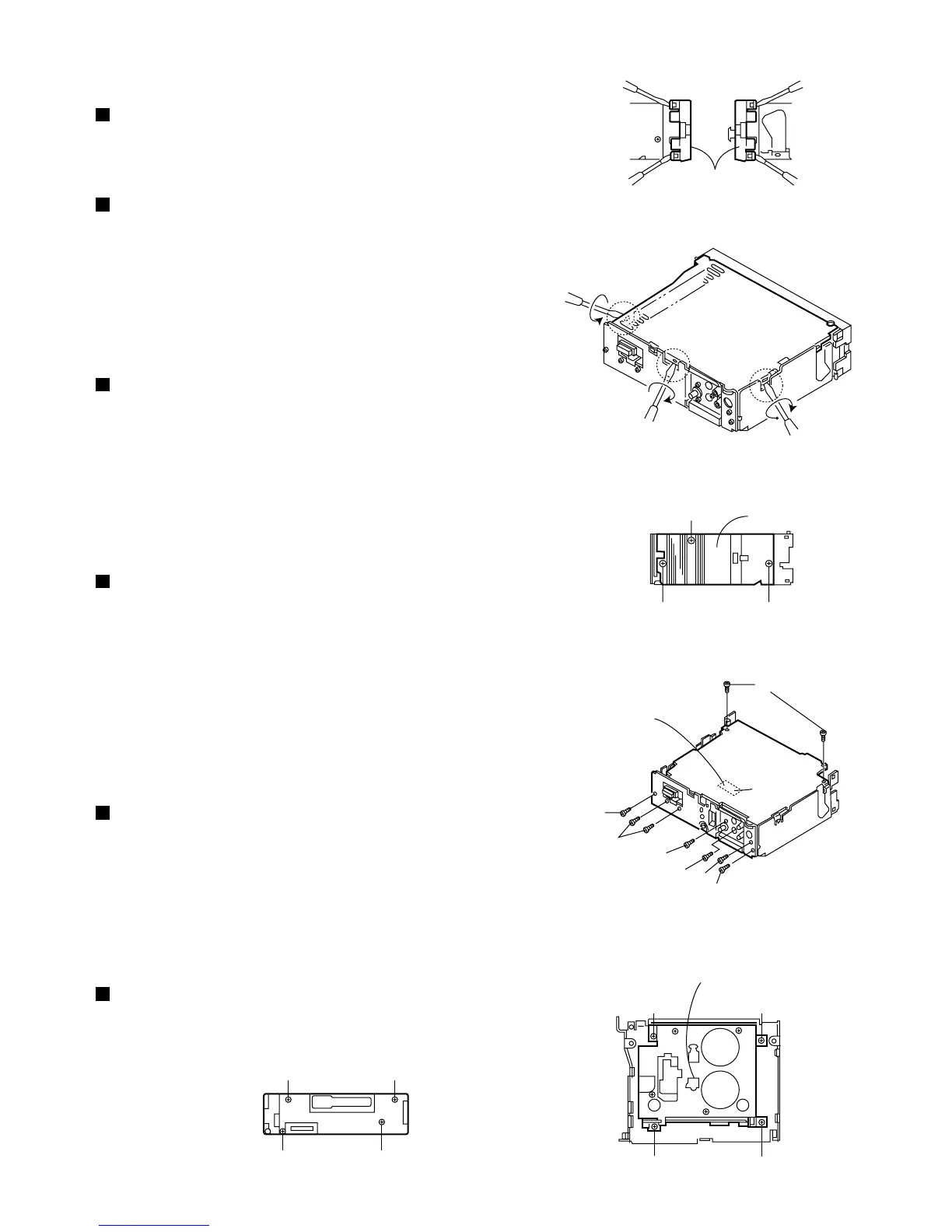
Removing the main board (see Fig.4)
Removing the rear panel (see Fig.4)
Removing the mechanism ass'y (see Fig.5)
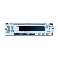
Removing the front panel unit (see Fig.6)
1.
2.
3.
Remove one screw A retaining the IC to the heat sink.
Remove two screws B to remove the heat sink.
Turn the upside down, the insert and turn the screwdriver
to remove the bottom cover and protect sheet.
1.
2.
3.
Remove two screws C retaining the rear panel to the
chassis.
Remove two screws D retaining the main board.
Lift up the main board to remove it. At this time,
remove the connector CP702 connecting the main
board and mechanism assembly.
1.
2.
3.
4.
Remove six screws retaining the jacks or the like.
Remove two screws E to the 16-pin jack.
Remove one screw F to remove the line-out jack.
Remove one screw G to remove the antenna jack.
Remove one screw H to remove the changer
controller jack.
1.
2.
3.
Remove four mechanism mounting screws I retaining
the mechanism assembly.
Remove four screws J retaining the cover.
Remove one screw which is the fixation of top cover
and the substrate.
1. Remove four screws K retaining the rear cover.
Front chassis
Fig. 1
Bottom cover
Fig. 2
Heat sink
Left side view
Fig. 3
Main board
CP702
Connection to the mechanism
connector position
Fig. 4
A
BB
D
C
E
H
F
G
C
Fig. 6
Mechanism ass'y
Fig. 5
JJ
JJ
KK
KK
 Loading...