1-6
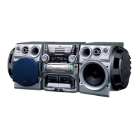
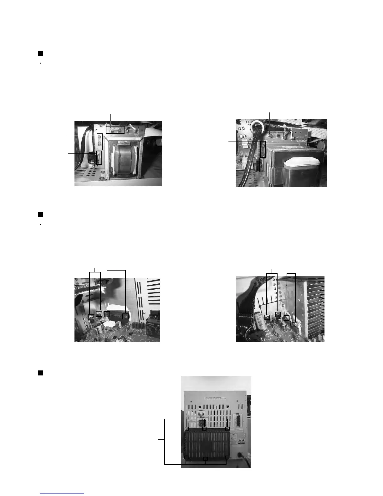
Fig.1(B)For MX-K30
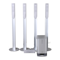
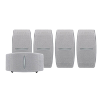
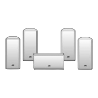
Fig.2For MX-K10
Fig.3For MX-K30
Fig.1(A)For MX-K10
[Caution] Be sure to use fuses with the specified
ratings.
Replacing the fuses (See Fig.1)
1.
Prior to performing the following procedure, remove
the left side BOARD
Replace the fuses inside.
1.
2.
Prior to performing the following procedure, remove
the top cover.
Remove the two screws "A" from the heat sink
Remove the solder fixing the power IC.
Replacing the power IC (See Fig.2 to 3)
<Disassembly of the main blocks of this set>
Replacement of the fuses and the power IC
1. Remove the six screws "B" from the back panel.
2. Pull the heat sink cover outward.
Replacing the heat sink cover
between the power IC.
Fuse (F951)
Fuse (F952)
1.6A 250V
FW 951
3.15A 250V
Fuse (F951)
1.6A 250V
FW 951
Fuse (F952)
1.6A 250V
W A
B
W
A
 Loading...