1-30 (No.YD091)
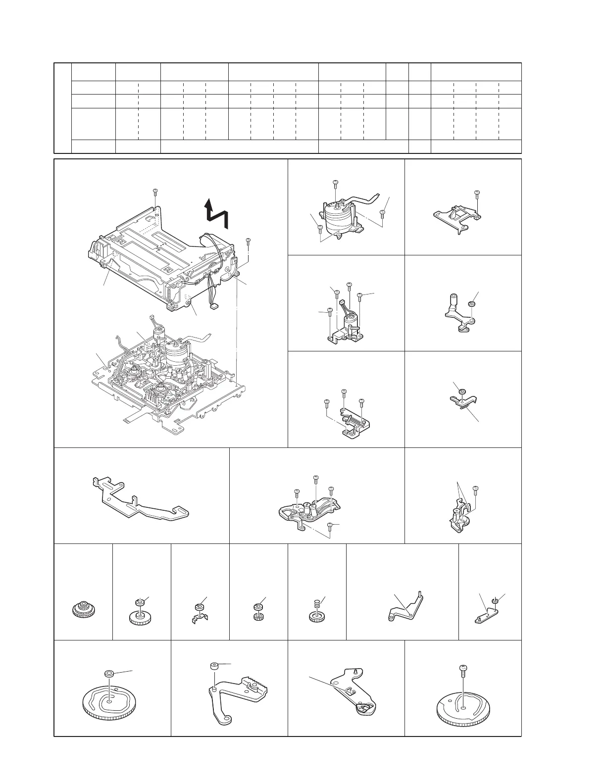
4.8 Mechanism disassembly/assembly sheet
Fig.4-8-1a
[A] Cassette housing assembly
S1×2, L1-L5
[1] Drum assembly
S2×3
S2×4
S2×3
[4] Reel cover assembly
S2, L6×2
[5]
Pinch roller arm assembly
W1, L7
P1, W1, L8
L12×2 S2×4 S2, L13×2
W1 W1 W3 P6 L15 W1, L16
W1 Collar L18 S2
[
A
][
1
][
2
][
3
][
4
][
7
][
11
]
1 18234567891011121314151617
S1
4-5-1 4-5-2 4-5-3
S2S1 S2 S2 S2 S2 S2 S2 S2 S2 S2 S2 S2 S3
4-5-4
4-5-6
S2 S2 S2
[2] Motor bracket assembly
[3] Middle catcher assembly
[17] Control plate [18] Guide rail (Take up) assembly [19] Guide rail (Supply)
assembly
[6] Sub brake assembly
[24] Center
gear
assembly
[27] Clutch
lock gear
(2)
[29] Tension control arm
assembly
[30]
Brake
control arm
assembly
[35] Main cam [36] Arm gear 1 assembly
[26] Push
plate
[25] Reel drive
pulley
assembly
[37]
Centering arm assembly
[28]
Clutch
lock
gear (1)
[38] Sub cam
5
(
S2
)
3
(
S2
)
4
(
S2
)
7
(
S2
)
6
(
S2
)
9
(
S2
)
8
(
S2
)
13
(
S2
)
12
(
S2
)
10
(
S2
)
11
(
S2
)
(
W1
)
(
W1
)
(
P1
)
24
(
S2
)
(
L13
)
20
(
S2
)
21
(
S2
)
22
(
S2
)
23
(
S2
)
(
W3
)
(
W1
)
(
W1
)
(
P6
)
(
L15
)
(
L16
) (
W1
)
(
W1
)
Collar
31
(
S2
)
1
(
S1
)
2
(
S1
)
(
L2
)
(
L4
)
(
L5
)
(
L1
)
(
L3
)
(
L18
)
Screw Management Table
Ref. Fig.
Fig. No.
No.
Type
Attachin

 Loading...