English 73
Working mode indicators
The following indicators are shown on the display when switching
to Working mode (PTO).
1 Function buttons
2 Working mode displays
3 Setting buttons
The function and settings buttons have already been described
previously.
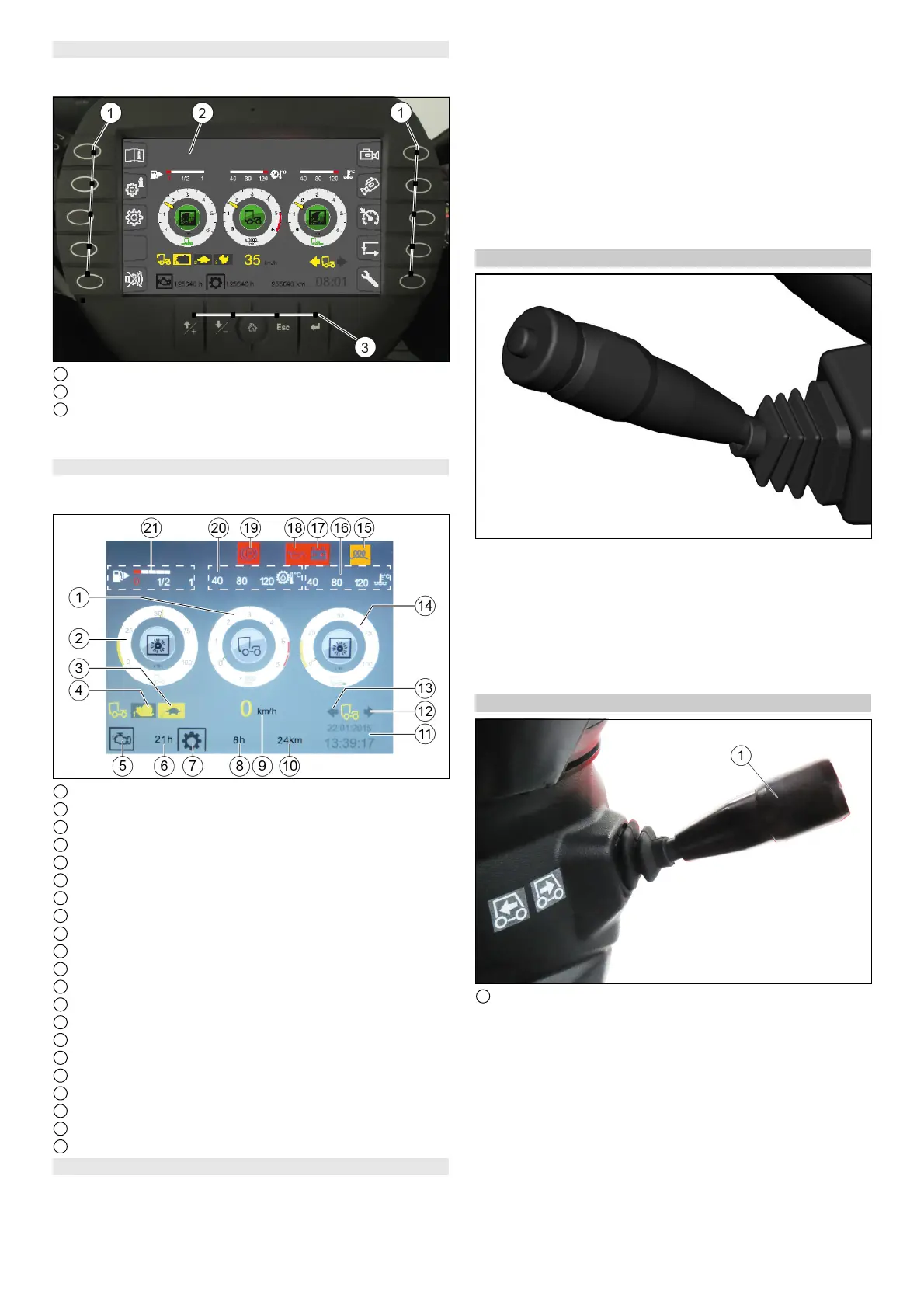
Working mode displays
The following indicators are shown on the display when switching
to Working mode (PTO).
1 Engine speed
2 Front attachment drive triggering level in %
3 Tortoise symbol (Fast mode indicator)
4 Snail symbol (Slow mode indicator)
5 Engine operating hours symbol
6 Operating hours counter
7 Working hours symbol (no function)
8 Working hours meter
9 Working speed
10 Mileage
11 Date and time
12 Travel direction backwards
13 Forwards direction of travel
14 Rear attachment drive triggering level in %
15 Preheating coil symbol
16 Engine coolant temperature
17 Battery charging monitor warning light
18 Engine oil pressure warning light
19 Parking brake warning light actuated
20 Hydraulic oil temperature
21 Fuel level indicator
Depressurise the hydraulic system (pressure relief)
The hydraulic system must be depressurised before disconnect-
ing the hydraulic hoses from the hydraulic connections.
1. Unplug the signal plug for attachment device detection (front).
2. Switch on the ignition (do not start the engine).
3. Switch on the PTO work hydraulics (at the arm rest control
panel).
4. Press the function key F 10 on the display.
5. Press function key F 6.
The rear hydraulic system is depressurised
6. Press function key F1.
The front hydraulic system is depressurised
7. Disconnect the hydraulic hoses.
8. Remove the attachment device.
Note
Attachment is performed in reverse sequence.
Multiswitch
Horn: Push the lever up.
Right turn signal: Lever up
Left turn signal: Lever down
High beam: Push down the lever with the high beam switched
on
Flashing: Pull the lever
Turn the ring: Switch on the windscreen wiper (intermittent
and constant)
Press the ring: Wiping with wiping water
Travel direction lever
1 Travel direction lever
Select the driving direction with the travel direction lever.
The following functions can be selected using the travel direction
lever, the selected programs are shown on the display.
Neutral position
Travel direction lever in the middle
Forwards direction of travel
Press travel direction lever upwards and push forwards
Travel direction backwards
Press travel direction lever upwards and pull backwards
Switchover between the fast (Hare) and slow (Tortoise) oper-
ating programs
Push the travel direction lever to the end position (travel direc-
tion lever must be in the neutral position).
 Loading...