I
Measurement
Adjustment
Item Cond~t~on
Spec~f~cation Remarks
Test
equipment
Unit
I
m~nal
--1
---
-
--
--
-
-
-
-
-
Set point 0 on the d~al
Should come ~n Check the
scale and the CAL control contact
wlth the scale (mecha
to the
~ndex When the CAL
,\I
11,
pointer nically)
control cal~brated at each
100 kHz
1s set at the Index,
check the dev~ation of the
d~al scale at each point
-
RlT Centered
RlT sw~tch ON
Set the VFO
maln control
to 5750 000 kHz
Less than 50 Hz
and OFF
RlT sw~tch ON
-1 5kHz or less
VFO 250
t
1 5kHz or more
RIT control fully counter- Reference to the
clockw~se
(@
pos~t~on) center
(9)
posl-
RlT control fully clock- tlon of the
wise (@ posltlon RIT control
RIT OFF
Install the 5750 kHz quartz
Normal
osc~lla
crystal into the socket on
tlon must be
the PLL
unlt
FIX ON R F VTVM
Remove the quartz crystal
from
~ts socket FIX OFF
8 Counter refe- Fcounter PLL
TP2
rence osc~llator
adjustment
glven In brackets are
obtalned
0 2 50 500 Unlt Part
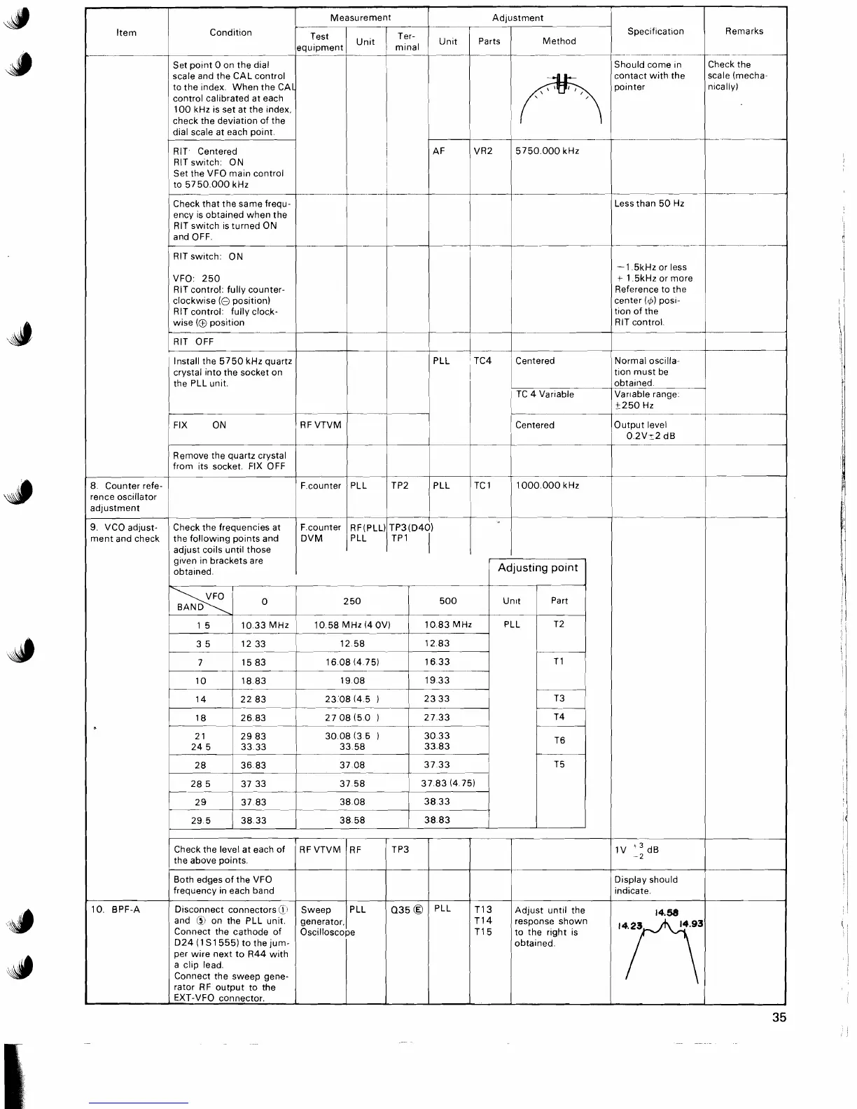
10 BPF-A
L
28 5
2
9
29
5
37 33
37 83
38 33
37 58
1
3783(4 75)
Check the level at each of
the above
polnts
Both edges of the VFO
frequency
In each band
D~sconnect connectors@l
and
6,
on the PLL unlt
Connect the cathode of
D24 (1
S1555) to the jum-
per wire next to R44 with
a
cllp lead
Connect the sweep gene-
rator RF output to the
EXT-VFO connector
1V ::dB
D~splay should
~nd~cate
RF VTVM
Sweep
RF
PLL
generator,(
Oscilloscope
TP3
035
0
TI4
TI5
PLL
response shown
to the
r~ght 1s
obta~ned
TI 3
Adjust
unt~l the
 Loading...