(8829
5
kHz (No 1 IF) -8374.0 kHz (CAR-2)
=
455 5 kHz)
Thus rhe second IF
slgnal
IS
shifted by +500 Hz, and as a
result the upper-s~de frequency components are cut by
500
Hz, as
illustrated
In (4) The frequency spectrum of the s~gnal
whlch has passed the second IF stage
IS
455 5 kHzk850 Hz
and the bandwidth
IS
1
7 kHz
If we convert the
srgnal fre-
quency to an
equlvalen~ one a1 the ANT Input, we obtaln
14.001 5 MHz+850 Hz In th~s case IF SHIFT
operation
is
not performed
Example
2
Bandw~d.rh 1
7
kHz
IF SHIFT 500 Hz
(poslt~ve sh~ft)
I
When the frequency of CAR-2 is lowered by 1 kHz with the
VBT control and that of
CAR-
1 ralsed by 500 Hz wlth the
SHIFT control, the
resulting
frequenc~es of CAR-2 and -1 are
CAR-1 88315
kHz(= 88315 kHz--0.5kHz*l+05
kHz"2)
CAR-2 8374 0 kHz
*I
Half the amount of frequency varied by VBT
*2 The amount of frequency rise with IF SHIFT
Let us examine the frequency spectrum of the ANT input
slgnal from the second IF component in Example 1
You
will
recall that the center frequency of the second IF
signal component is 455.5 kHz and the upper
limit 455.5
kHz+850 Hz
The signal is
455.5 kHz f8374.0 kHz= 8829.5 kHz in the
flrst IF and the lower llmlt 8829.5 kHz-850 Hz. As a result.
signal components which have passed an 8830 kHz
fllter
and a 455 kHz fllter are the same as In Example 1 But the
VCO output is 22.8315 MHz because CAR-1 which was
8831
0 kHz
111
Exarrlple 1 is 8831 5 kHz in Example 2 Slnce
the converted equrvalent frequency range at the flrst IF is
8829.5 kHzk850 Hz, ~ts equivalent at the ANT Input
IS
14.002 MHzk850 Hz.
(22 831
5
MHz-8.8295 MHz= 14.002 MHz)
This means that a signal 1 7 kHz
In bandwldth
IS
received
wlth a shift of
+
500 Hz. In other words, the filter
characteristics have been changed appropriately
As you may have noted in Examples 1 and
2,
the V.BT and IF
SHIFT controls operate separately Therefore, it
IS
possrble
to control the bandwidth alone whlle keeping the IF SHIFT
unchanged, or control IF SHIFT while keeping the
bandwldth
unchanged
3. NOTCH [in IF unit (X48-1290-00)
1
4
7
Thls
IS
a brtdged-T filter
consisting
of
L,
C, and R components.
The notch
IS
provlded In the 455 kHz IF Normally, the width
of the null would be broad at 455 kHz. Actually a sharp
notch is
provlded by adding an active circuit which applies
posltive feedback to raise the Q. Q5 and 06 (2SC1815Y)
are a Q-multiplier
Q7 (2SC181 5Y) is a buffer ampllfier
4. Speech processor [in IF unit (X48-1290-00)
]
&Y
T~IS speech processor
IS
an RF cl~pper The recelver uses
two Intermediate
frequencles and two filters for VBT In the
venlenr for lnstalllng RF clippers between the stages. The
455 kHz SSB signal is clipped and then
c0nverte.d to an 8.83
Mliz signal, and then routed through an
8.83
MHz
SSB
filter
to remove splatter components generated during
clipplng
Q24 (2SC1815Y) is a processor amplifier, Q26 (TA7302P) a
llmitlng
amplifier,
Q27 (3SK73GR)
a
control ampllfier, and
Q25
(2SC1815Y) and Q37 (2SA1015Y) compose
a
com-
presslon meter amplifier The compresslon meter reads the
mean compresston level.
5.
Final-stage RF NFB
Negatlve feedback
IS
applled to the drlver from the final out-
pul stage via C6, a
3PF.
3KV capacitor to reduce Inter-
modulation distortion.
6.
R
IT/XIT Operations
In addition to the conventional RIT, the transmission frequen-
cy can be
varled wrth the XIT control
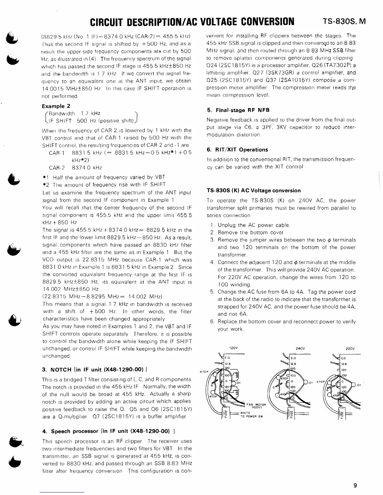
TS-830s
(K)
AC
Voltage conversion
To operate the TS-830s
(K)
on 240V AC, the power
transformer split
primaries
must be rewired from parallel to
series connection
1. Unplug the AC power cable.
2 Remove the bottom cover
3. Remove the jumper wires between the two
4
terminals
and two 120 terminals on the bottom of the power
transformer.
4. Connect the adjacent 120 and
4
terminals at the middle
of the transformer.
'This will provide 240V AC operation.
For 220V AC operation, change the wires from 120 to
100 winding.
5. Change the AC fuse from 6A to 4A. Tag the power cord
at the back of the radio to indicate that the transformer is
strapped for
240V AC, and the power fuse should be 4A.
and not 6A.
6. Replace
.the bottom cover and reconnect power to verify
your work.
FAN
MOTOR
(iOOV)
ITE
POWER SW
transmltter, an SSB slgnal
IS
generated at 455 kHz,
IS
con-
&
verted to 8830 kHz, and passed through an SSB 8.83 MHz
filter after frequency conversion
Thls configuration
IS
con-
 Loading...