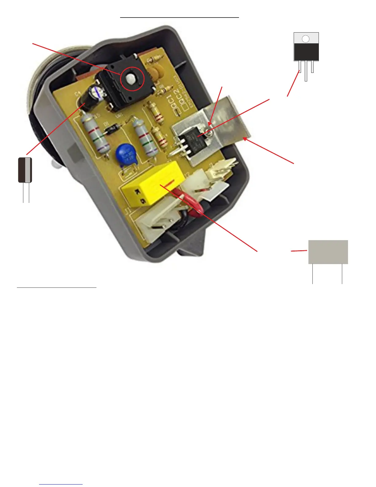
Triac
220uF 16V
_ _ _
220uF
Capacitor
150nF 275V X2
150nF
Capacitor
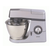
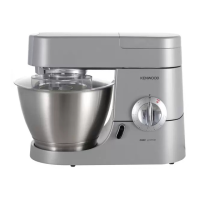
SPEED CONTROLLER PCB ASSEMBLY
NUT AND BOLT
HEATSINK
+
_
Working on the Rear of the board,
desolder and remove the old
components.
SPINDLE PASSES THROUGH HOLE
IN SPEED CONTROL
FITTING THE NEW PARTS
Refit board into plastic case, ensuring the control splidle passes through the hole in the speed control as
shown on previous page. Snap on plastic lid.
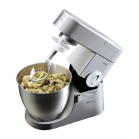
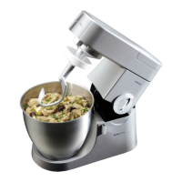
Refit contolller to mixer and reconnect plugs to connectors on controller
Refit motor cover and screw silver arm back into place.
Test your mixer
Fit the 220uF capacitor so that the ‘-’ stripe is facing
away from the edge of the board as shown
Fit the new triac as shown, forming the legs to fit the holes
in the board and refitting the heatsink and nut and bolt.
Tighten the nut and bolt before soldering the legs.
Working on the rear of the board, with the legs uncut,
solder the components to the PCB then cut the legs
where they emerge from the solder joints.
 Loading...