EasyManua.ls Logo

Kenwood KRF-V6030D Service Manual

Kenwood KRF-V6030D
49 pages
To Next Page IconTo Next Page
Page #1 background imageLoading...
Page #1 background image
AUDIO
VIDEO
SURROUND
RECEIVER
Y
KRF-V4530D
KENWOOD
KRF-V5030D/V5030DE/V5030D-S
KRF-V6030D/V6030DE/V6030D-S
VR-405/406/414
SERVICE
MANUAL
eens
Note:
On
circuit
description,
please
refer
to
KRF-V7030D
service
manual(B51-5598-00).
Knob
Front
glass
Panel
(K29-7688-03)
(B10-3550-02)
;
(A60-1757-11)
VOLUME
CONTROL
Sragper
INPUT
SELECTOR
170
SETUP
PUTOOE
——_OIMER
MONITOR
a
i
_——
ewe
|
ff
O
SOUND
LISTEN
MODE
SOURCE
DIRECT
r
y
‘AUTO
EMORY
CICICS
|
=
Sec
aeenae
fn
6CHINPUT
—————————_E
_—CVV/'aVn—_—_—_—
FOR
EXTRA
DIGITAL
AUDIO
FORMAT
Knob
Knob
(K27-2385-04)
(K29-7688-03)
Knob
Knob
Knob
Phone
jack
Knob
(K29-7676-12)
(K29-7682-14)
(K29-7679-04)
(E11-0272-05)
(K29-7685-03)
Pin
jack
Pin
jack
Optical
receiving
module
Power
cord
bushing
AC
power
cord
(E63-1138-05)
(E63-1080-05)
(W02-2716-05)
(J42-0083-05)
(E30-2942-05)
Pin
jack
Pin
jack
Miniature
phone
jack
Metallic
cabinet
(E63-1139-05)
(E63-1141-05)
(E11-0293-05)
(A01-3734-01)
FRONT
SPEAKERS
CENTER
SPEAKERS
REC
)6
-
160)[BIUE}
(8
-
160)
GREEN
FRONT
SPEAKERS
(8-160)
d
=
OGITALIN
|
1
PAWS
ma
Cy
S)-
Ee
(roa)
aE
SSVIES
SD
4
A
erm
O
bu
SURROUND
SPEAKERS
MomTapet
woe
SUS
WOOFER
PRE
OUT
Lock
terminal
board
Pin
jack
Pin
jack
Screw
terminal
board
Lock
terminal
board
(09-0
140-08)
(E20-0321-05)
(E63-1143-05)
(E63-1146-05)
(E70-0049-05)
(E70-0057-05)
70%
Taw
IIlust.
is
KRF-V6030D-S(M).

Other manuals for Kenwood KRF-V6030D

Question and Answer IconNeed help?

Do you have a question about the Kenwood KRF-V6030D and is the answer not in the manual?

Kenwood KRF-V6030D Specifications

General IconGeneral
BrandKenwood
ModelKRF-V6030D
CategoryReceiver
LanguageEnglish

Summary

Controls Overview

Front Panel Controls

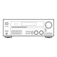
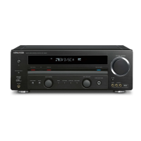
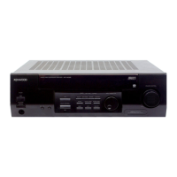
Overview of buttons, knobs, and displays on the front panel.

Remote Control Operations

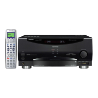
Detailed explanation of keys and functions for RC-R0609 and RC-R0509 remotes.

Block Diagram

Adjustment Procedures

FM Section Adjustments

Procedures for adjusting FM discriminator and tuning level for optimal performance.

Parts Descriptions

Tuner Unit Schematic

Schematic Diagrams

Power Supply, Protection, and Muting Circuits

Schematics for power supply, protection, muting, and transformer connections.

Parts List

Component Part Numbers and Descriptions

Comprehensive list of parts with their respective numbers, descriptions, and destination codes.

Specifications

Audio and Video Specifications

Power output, frequency response, sensitivity, and video interface details.

Related product manuals