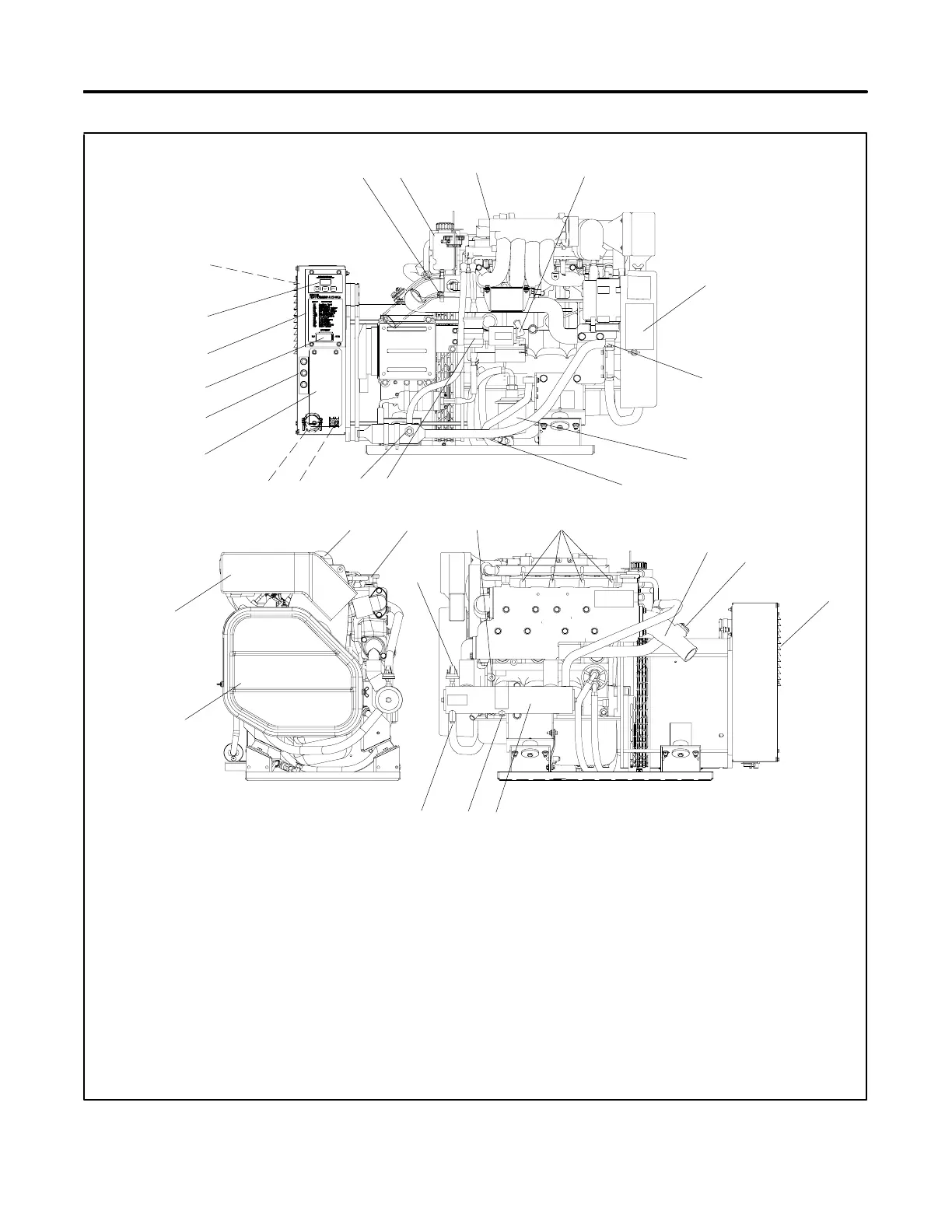
TP-6323 3/06 13Section 1 Service Views
Section 1 S ervice Views
6
3
21
30 27
24
25
5
9
8
13
23
7
16
10
12
22
26
19
GM34482-
17
SERVICE-SIDE VIEW
ENGINE-END VIEW
1
31
18
15
2
20
1. Oil check
2. Coolant overflow bottle
3. Oil fill (on valve cover)
4. Positive (+) battery connection point
5. Nameplate
6. Seawater pump (water inlet)
7. Lube oil filter
8. Oil drain valve
9. Fuel filter
10. Fuel feed pump (fuel inlet)
11. Remote customer interface connector (nonservice side)
12. Customer load lead access (nonservice side)
13. AC circuit breaker panel
14. Fuse panel location (F1, F2, and F3)
15. Generator set master switch
16. ADC 2100 controller
17. Runtime hour display
18. Fuse location inside junction box (F4, F5, F6, and F7)
19. Air intake silencer/backfire flame arrestor
20. Belt guard
21. Anticorrosion zinc anode (seawater drain)
22. Coolant drain
23. Heat exchanger
24. Cooling air inlet
25. High exhaust temperature switch
26. Mixing elbow, water outlet/exhaust outlet
27. Spark plugs
28. Negative (--) battery connection point
29. Oil pressure switch
30. Engine water fill (coolant fill location after draining coolant)
31. Lifting eye
Note: Consult your distributor/dealer or the service manual for
items not shown.
NONSERVICE-SIDE VIEW
29
4
28
11
14
Figure 1-1 Service Views
 Loading...


