TP-6196 10/0936 Section 4 ADC 2100 and DC 2200 Controllers
4.2 Controller Display and Keypad
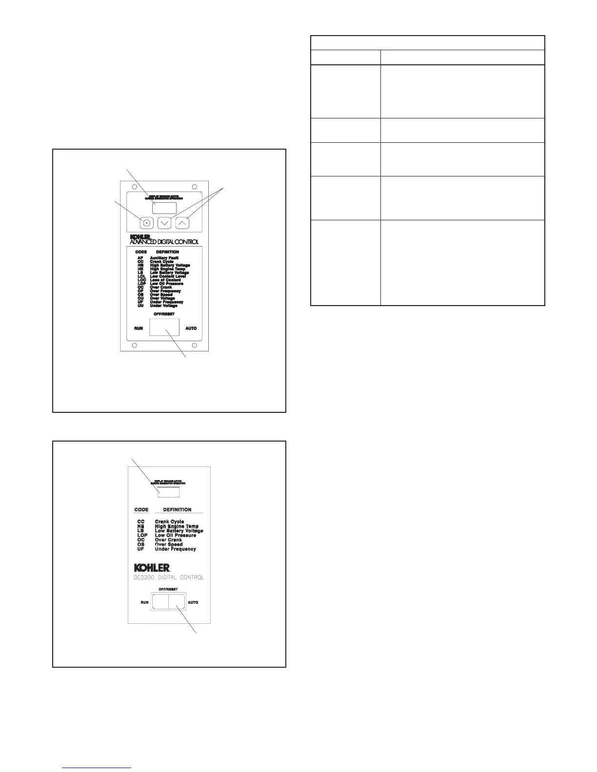
The ADC 2100 controller has an LED display and a
three-button keypad. See Figure 4-2. The DC 2200
controller has a display, but no keypad. See Figure 4-3.
The LED display shows runtime hours, fault codes,
application program version number, or controller
parameters during configuration and adjustment. See
Figure 4-4.
1
2
4
3
1. LED display
2. Select button (use for setup and adjustment only)
3. Up and down arrow buttons (use for setupand adjustmentonly)
4. Generator set master switch
GM28707A-C
Figure 4-2 ADC 2100 Controller
GM39579
1. LED display
2. Generator set master switch
1
4
Figure 4-3 DC 2200 Controller
Controller Display
Item Description
Crank
indication
Displays CC_1, CC_2, or CC_3 t o
indicate the first, second or third attempt
to st art the engine. The last digit
flashes during the crank cycle rest
periods.
Runtime hours Displ ays total generator set runtime
hours when no other code is displayed.
Fault codes Flashes a 2- or 3-letter fault code to
indicate various fault conditions. See
Section 4.4.
System
parameters
Displays 2-letter codes or 4-digit
alphanumeric codes during system
configuration or adjustment. S ee
Section 4.5.
Application
program
version number
ADC 2100: Displays the version
number of the controller’s application
program before entering the
configuration or adjustment mode. See
Section 4.5.4.
DC 2200: Application program version
number is displayed at controller
powerup.
Figure 4-4 Controller LED Display
The ADC 2100 keypad is used to enter the controller’s
configuration and adjustment menus and to change the
controller settings. A password key sequence is
required to enter the configuration and adjustment
menus. Section 4.5 contains the instructions to enter
the configuration and adjustment menus and change
the settings using the controller keypad.

 Loading...


