25
EFI System
66 690 07 Rev. -- KohlerEngines.com
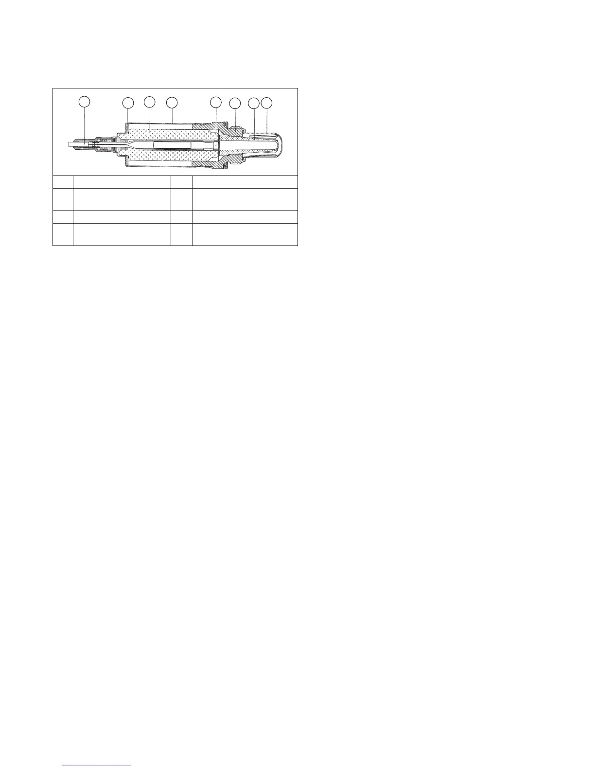
OXYGEN SENSOR
Cutaway of Oxygen Sensor
A
B
C
D
E
F G
H
A Connection Cable B Disc Spring
C
Ceramic Support
Tube
D Protective Sleeve
E Contact Element F Sensor Housing
G
Active Ceramic
Sensor
H Protective Tube
NOTE: All tests should be conducted with a good
quality, high-impedance, digital VOA meter for
accurate results.
Like other sensors already discussed, oxygen sensor is
a non-serviceable component. Complete replacement is
required if it is faulty. Sensor and wiring harness can be
checked as follows.
1. Oxygen sensor must be hot (minimum of 400°C,
752°F). Run engine for about 5 minutes. With engine
running, disconnect oxygen sensor lead from wiring
harness. Set VOA meter for DC volts and connect
red lead to disconnected sensor lead, and black lead
to sensor shell. Look for a voltage reading from
0.2 v-1.0 v.
a. If voltage is in specifi ed range, go to Step 2.
b. If voltage is not in specifi ed range, reconnect
oxygen sensor lead. With lead connected, probe
or connect sensor connection with red VOA meter
lead. Attach black VOA meter lead to a good
ground location. Start and run engine at 3/4
throttle and note voltage reading being signaled
by oxygen sensor. Reading should cycle between
0.2 v and 1.0 v, which indicates oxygen sensor is
functioning normally and fuel delivery is within
prescribed parameters. If voltage readings show
a steady decline, rev engine and check indicated
reading again. If voltage momentarily increases
and then again declines, without cycling, engine
may be running lean due to incorrect TPS
initialization. Shut off engine, perform TPS
initialization, and then repeat test. If TPS
initialization cannot be achieved, perform step c.
c. Replace oxygen sensor (see next page). Run
engine long enough to bring new sensor up to
temperature and repeat output test from step 1.
Cycling voltage from 0.2 to 1.0 v should be
indicated.
2. Move black voltmeter lead to engine ground location
and repeat output test. Same voltage (0.2 v-1.0 v)
should be indicated.
a. If same voltage reading exists, go on to Step 3.
b. If voltage output is no longer correct, a bad
ground path exists between sensor and engine
ground. Touch black lead at various points,
backtracking from engine ground back toward
sensor, watching for a voltage change at each
location. If correct voltage reading reappears at
some point, check for a problem (rust, corrosion,
loose joint or connection) between that point and
previous checkpoint. For example, if reading is
too low at points on crankcase, but correct
voltage is indicated when black lead is touched to
skin of muffl er, fl ange joints at exhaust ports
become suspect.
3. With sensor still hot (minimum of 400°C,752°F),
switch meter to Rx1K or Rx2K scale and check
resistance between sensor lead and sensor case. It
should be less than 2.0 KΩ.
a. If resistance is less than 2.0 KΩ go to Step 4.
b. If resistance is greater than 2.0 KΩ, oxygen
sensor is bad, replace it.
4. Allow sensor to cool (less than 60°C, 140°F) and
retest resistance with meter set on Rx1M scale. With
sensor cool, resistance should be greater than 1.0
MΩ.
a. If resistance is greater than 1.0 MΩ go to Step 5.
b. If resistance is less than 1.0 MΩ, sensor is bad,
replace it.
5. With oxygen sensor disconnected and engine not
running, disconnect main harness connector from
ECU and set meter to Rx1 scale. Check for
continuity from pin #19 of ECU connector to shell of
oxygen sensor, and from pin #20 to sensor terminal
of main harness. Both tests should indicate
continuity.
a. If there is no continuity displayed in either of
tests, check harness circuit for breaks or damage,
and connections for poor contact, moisture, or
corrosion. If no continuity was found in fi rst test,
also check for a poor/broken ground path back
through exhaust system, engine, and mounting
(sensor is grounded through its shell).
b. If continuity is indicated, go to step 6.
6. With key switch in ON/RUN position, using a high
impedance voltmeter, check voltage from wiring
harness oxygen sensor connector to engine ground
location. Look for a steady voltage from 350-550 mv
(0.35-0.55 v).
a. If voltage reading is not as specifi ed, move black
voltmeter lead to negative post of battery, to be
certain of a good ground. If voltage is still not
correct, ECU is probably bad.
b. If voltage readings are correct, clear fault codes
and run engine to check if any fault codes
reappear.
To Replace Oxygen Sensor
1. Disconnect oxygen sensor connector from wiring
harness.
2. Loosen and remove oxygen sensor from exhaust
manifold/muffl er assembly.
 Loading...