Governor System
4124 690 06 Rev. P KohlerEngines.com
Adjustment
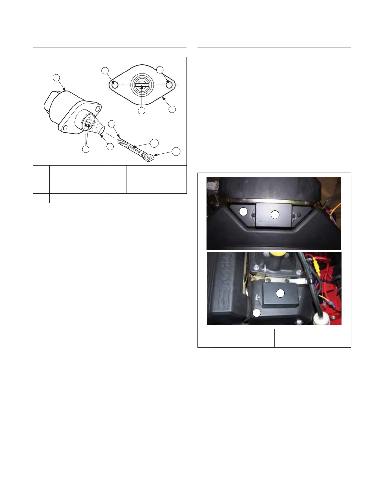
DLA Details
C
C
A
A
B
B
F
D
G
E
A DLA B Mounting Holes
C Clevis D Keyway
E Clevis Shaft F Rubber Boot
G Keys
DLA must be in fully retracted position during assembly.
Full range of throttle plate movement will not be
achieved if DLA is partially extended when assembled.
Loosen DLA mounting plate screws located on top of
actuator plate. With throttle linkage centered in U-Clip or
secured with a retaining clip at end of DLA shaft, press
and hold clevis shaft into actuator, while sliding DLA
bracket assembly back until throttle plate is fully open.
Torque mounting plate screws to 2.5 N·m (22 in. lb.).
If clevis shaft becomes over extended or disconnected
from actuator, replace DLA or reinstall clevis shaft as
follows:
1. Disconnect linkage and remove DLA from bracket.
2. Remove clevis shaft completely out of DLA.
3. Reinstall rubber boot onto DLA if required.
4. Place clevis shaft into actuator. Rotate clevis shaft
clockwise 3 full turns, applying slight pressure, until
you feel clevis shaft keyway make contact with key
in actuator. When clevis is installed properly, fl at of
clevis will be aligned with two DLA mounting holes.
NOTE: Continuing to rotate clevis shaft after it has
made contact with keyway will damage keyway
or actuator.
5. Confi rm that key and keyway are in alignment, by
hand, press clevis shaft into actuator. It will take a
reasonable amount of pressure to do this. If shaft will
not move inward, do not force it. Remove clevis
shaft and repeat previous step.
6. Reinstall DLA into bracket and connect linkage.
Troubleshooting
Engine Starts But Will Not Continue to Run
1. Check linkage connection between DLA and throttle
plate.
2. Verify throttle plate is opened during start procedure.
Engine is unlikely to start if throttle plate is not
opened. Normal opening may be a small amount of
a few degrees.
3. Test OEM control system for output voltage. Refer to
equipment manufacturer’s manual.
4. Check wire harness and connections.
Engine Does Not Run At Expected Speed
1. Check to see that throttle linkage and DLA have full
range of motion having no mechanical interference.
2. Test OEM control system for output voltage. Refer to
equipment manufacturer’s manual.
GCU Locations
A
B
C
D
A Panel B GCU
C Blower Housing D GCU
GCU is either secured to a panel on front of engine or to
#1 side of blower housing.
 Loading...