92
Disassembly/Inspection and Service
KohlerEngines.com 24 690 06 Rev. P
Remove Throttle and Choke Controls (if equipped)
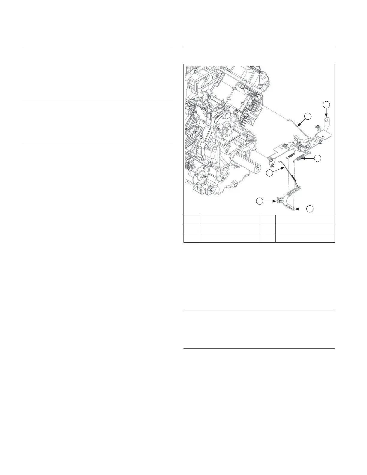
Control Bracket Components (Mechanical
Governor)
E
F
D
C
B
A
A Choke Linkage B Control Bracket
C Spring D Governor Lever
E Nut F Throttle Linkage
1. Remove screws securing control bracket and rear air
cleaner bracket (some models) to cylinder heads.
2. Mark spring hole locations and disconnect spring
from governor lever.
3. Remove choke linkage (if equipped) from choke
actuator lever and carburetor.
Remove External Governor Controls (Mechanical
Governor)
Loosen nut and remove governor lever from cross shaft.
Leave lever attached to throttle linkage and lay assembly
on top of crankcase.
Remove External Governor Controls (Electronic
Governor)
1. Disconnect stepper motor connector from wiring
harness.
2. Unhook linkage spring and disconnect bushing from
throttle linkage. Remove linkage from stepper motor.
3. Remove screws securing control bracket and rear air
cleaner bracket (some models) to cylinder heads.
4. Disconnect choke linkage (if equipped) from control
lever on control bracket.
5. Remove control bracket with stepper motor.
Remove Control Panel (if equipped)
1. Disconnect Oil Sentry
™
indicator light wires.
2. Disconnect choke control cable from control bracket.
3. Disconnect throttle control cable or shaft.
4. Remove panel from blower housing.
Remove Debris Shield and Control Cable Assembly
(if equipped)
1. Remove screw securing cable to control bracket.
2. Disconnect choke control cable from control bracket.
3. Remove screws securing debris shield and control
cable assembly to blower housing.
Remove Idle Solenoid (if equipped)
1. Disconnect fl ag terminals from idle solenoid.
2. Mark spring hole location and disconnect governor
spring from governor lever. Other end of spring can
stay in speed control rod.
3. Remove screws securing rear air cleaner bracket to
cylinder heads.
NOTE: Top screw on #2 cylinder also secures ground
lead ring terminal.
4. Disconnect bushing from throttle linkage. Mark
locations of linkage and linkage spring. Unhook
linkage spring from governor lever. Remove throttle
linkage from governor lever.
5. Take note of roll pin hole location in governor lever,
then remove screws securing solenoid bracket
assembly to closure plate. Note position of washer
and which screw it is on for reassembly.
6. Loosen nut and remove governor lever from cross
shaft.
 Loading...