11.9
Section 11
Reassembly
11
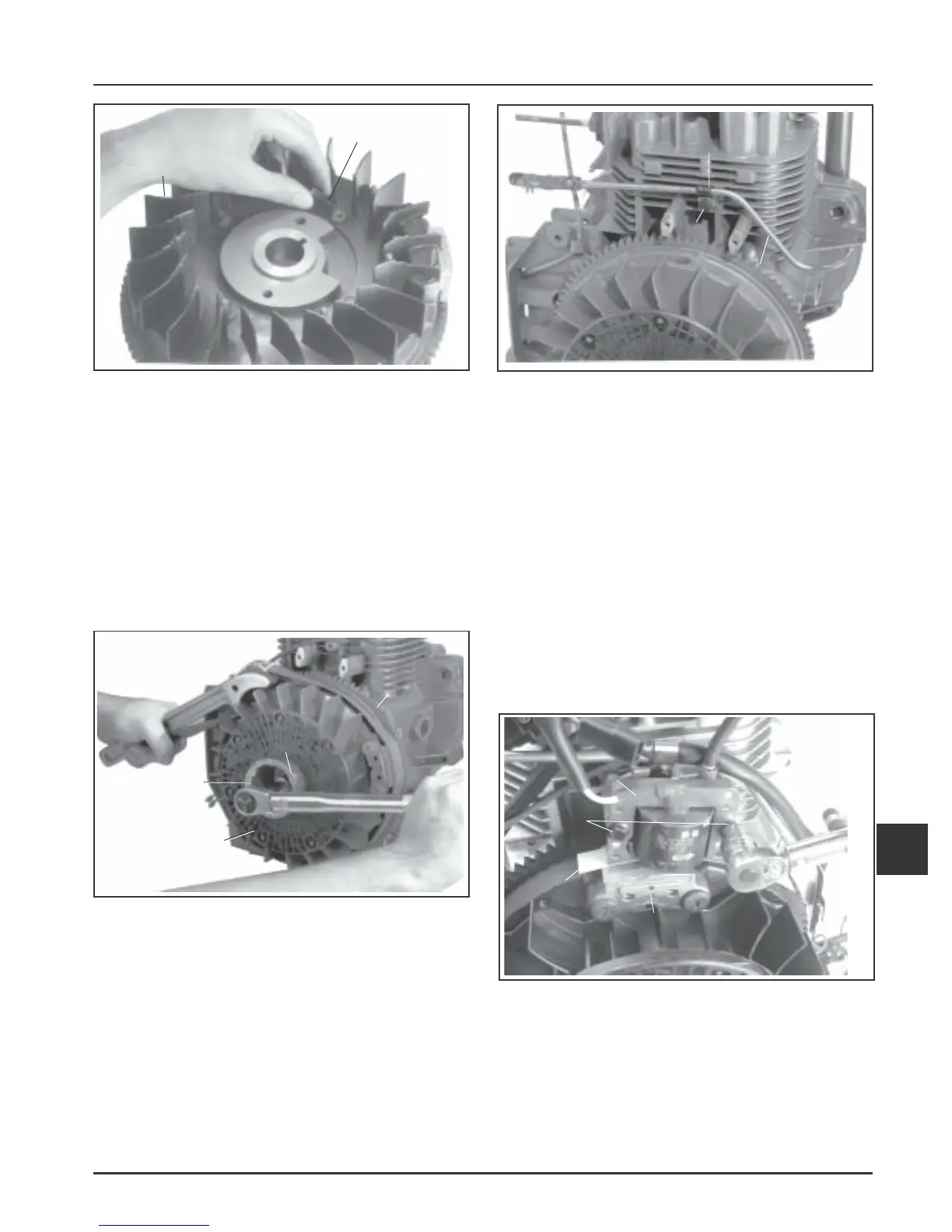
Figure 11-25. Installing Fan To Flywheel.
3. Install the woodruff key into the keyway in the
crankshaft.
4. Place the flywheel over the keyway/crankshaft.
Install grass screen, drive cup, plain washer (flat
side of plain washer towards the drive cup), and
the hex flange screw. See Figure 11-26.
5. Hold the flywheel with the strap wrench or
holding tool and torque the hex flange screw to
66.4 N·m (49 ft. lb.). See Figure 11-26.
Figure 11-27. Installing Fuel Line.
Install Ignition Module
1. Rotate the flywheel so the magnet is away from
the ignition module bosses. Install the ignition
module to the bosses on the crankcase. The
directional arrow denoting proper flywheel
rotation must be up. Move the module as far
from the flywheel/magnet as possible. Tighten
the hex flange screws slightly.
2. Insert a 25 mm (0.010 in) flat feeler gauge or shim
stock between the magnet and ignition module.
See Figure 11-28.
Loosen the hex flange screws so the magnet pulls
the module against the feeler gauge.
Figure 11-26. Installing Flywheel.
Install Fuel Line
1. Install the fuel line, clamp and hex flange screw.
See Figure 11-27.
Clip
Hex Flange
Screw
Fuel Line
Hex Flange
Screws
Magnet
Flat Feeler
Gauge
Ignition Module
Figure 11-28. Installing Ignition Module.
Fan
Flywheel
Hex Flange
Screws (4)
Flywheel
Plain Washer &
Hex Flange Screw
Drive Cup
Grass Screen
 Loading...


