11.11
Section 11
Reassembly
11
Figure 11-33. Separate Pivot/Rocker Arm Styles.
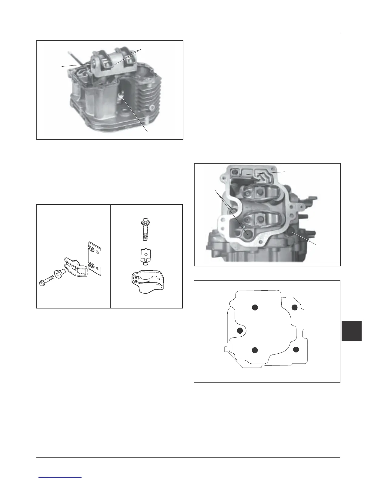
5. Install the breather reed, reed retainer and secure
with the M5 hex flange screw. Torque the screw
to 6.2 N·m (55 in. lb) in new hole, or 3.9 N·m
(35 in. lb.) in used hole. See Figure 11-34.
6. Install exhaust studs (if removed previously, or
new head is being installed). The threaded end
with the oval point or identification symbol must
be out.
Install Cylinder Head
1. Rotate the crankshaft to TDC of the compression
stoke and make sure the lifters are installed in the
lifter bores with the socket up.
2. Reinstall the push rods in their original position.
Figure 11-32. Installing Rocker Arms.
Heads with Separate Pivots/Rocker Arms
Position the pivots in the sockets of the rocker
arms. Insert the screws through the pivots,
rocker arms, and guide plate (some models only).
Start the screws into the head and finger tighten
only at this time. See Figure 11-33.
Rocker
Shaft
Rocker Arms
Spark Plug
Figure 11-34. Installing Cylinder Head.
3. Install a new cylinder head gasket and the
cylinder head assembly on the crankcase. Slide
the spacer and washer onto one of the new head
bolts, and install it in the #5 position (between
the intake and exhaust ports). See Figure 11-34. If
the engine has a high temperature cutout switch,
insert the new long (90 mm) head bolt through
the special washer (flat on one edge) and cutout
switch, and install it in the #1 position. See Figure
11-35. Install the remaining new head bolts.
Following the sequence in Figure 11-35, torque
the bolts to 24 N·m (18 ft. lb.). Then repeat the
sequence to a final torque of 48.9 N·m (36 ft. lb.).
NOTE: When installing cylinder heads, new
head bolts should always be used.
Figure 11-35. Cylinder Head Fastener Torque
Sequence.
Hex Flange
Screws
Breather Reed
Retainer and
Breather Reed
Hex
Flange
Screw
and
Spacer
1
2
3
4
5
 Loading...


