9.14
Section 9
Disassembly
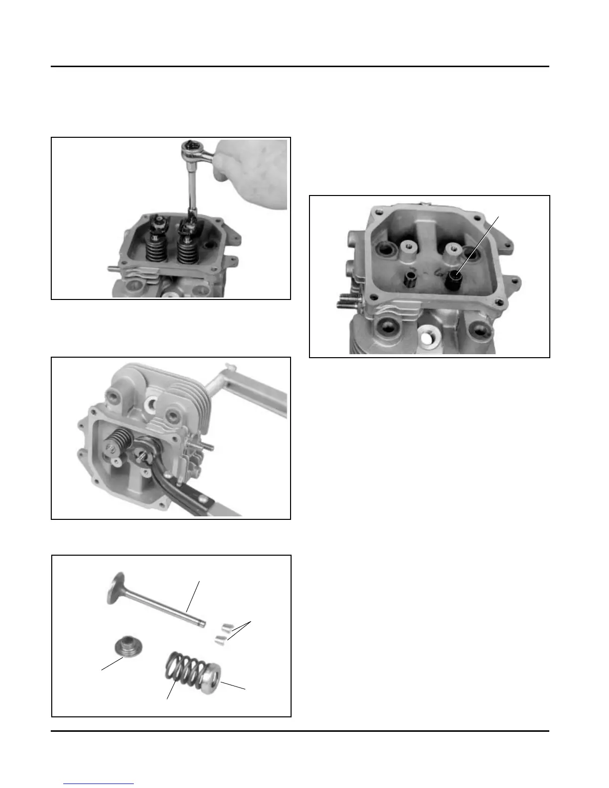
Figure 9-53. Valve Train Components.
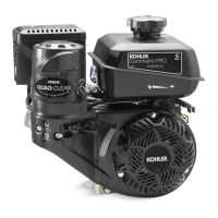
Figure 9-51. Removing Rocker Arms.
2. Compress the valve springs using a valve spring
compressor. See Figure 9-52.
Figure 9-52. Removing Valves with Valve Spring
Compressor.
Disassemble Cylinder Heads
1. Remove the two hex. flange screws, rocker arm
pivots and rocker arms from the cylinder head.
See Figure 9-51.
3. Once the valve spring is compressed, remove the
following items. See Figures 9-53 and 9-54.
• Valve spring keepers
• Valve spring retainers
• Valve springs
• Valve spring caps
• Intake and exhaust valves (mark position)
• Valve stem seals (intake valve only)
Valve
Retainer
Spring
Keepers
Cap
Valve Seal
Figure 9-54. Intake Valve Seal Location.
NOTE: These engines use valve stem seals on the
intake valves. Use a new seal whenever valve
is removed or if the seal is deteriorated in any
way. Never reuse an old seal.
4. Repeat the above procedure for the other cylinder
head. Do not interchange parts from one cylinder
head to the other.
Remove Grass Screen and Fan
1. Small metal retainers are typically attached on
three of the seven mounting posts for positive
retention of the plastic grass screen. Use a hook-
end tool next to the post and pull outward to
separate each of the small metal retainers. Then
unsnap the fan from the remaining mounting
posts. See Figure 9-55.
 Loading...