9.16
Section 9
Disassembly
Figure 9-63. Breaking Seal on Top Splitting Tab.
Governor Gear Assembly
The governor gear assembly is located inside the
closure plate. If service is required, refer to the service
procedures under ‘‘Governor Gear Assembly’’ in
Section 10.
Oil Pump Assembly
The oil pump is mounted to the inside of the closure
plate. If service is required, refer to the service
procedures under ‘‘Oil Pump Assembly’’ in Section 10.
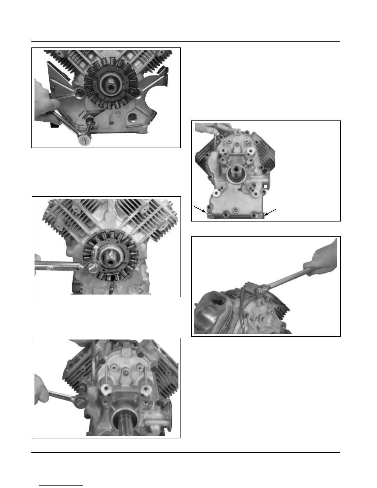
Figure 9-59. Removing Backing Plates and Stator
Wire Bracket.
2. Remove the two hex. head screws and stator.
See Figure 9-60. Note the routing of the stator
lead in the channel.
Figure 9-60. Removing Stator.
Remove Closure Plate Assembly
1. Remove the ten hex. flange screws securing the
closure plate to the crankcase. See Figure 9-61.
2. Locate the three splitting tabs that are cast into
the perimeter of the closure plate. Insert the drive
end of a 1/2" breaker bar between the top splitting
tab and the crankcase. Hold the handle horizontal
and pull toward you to break the RTV seal. If
necessary, pry at the bottom tabs also. See
Figures 9-62 and 9-63. Do not pry on the sealing
surfaces as this could cause leaks. Carefully pull
closure plate from crankcase.
Figure 9-61. Removing the Ten Closure Plate
Fasteners.
Figure 9-62. Location of Three Splitting Tabs.
 Loading...