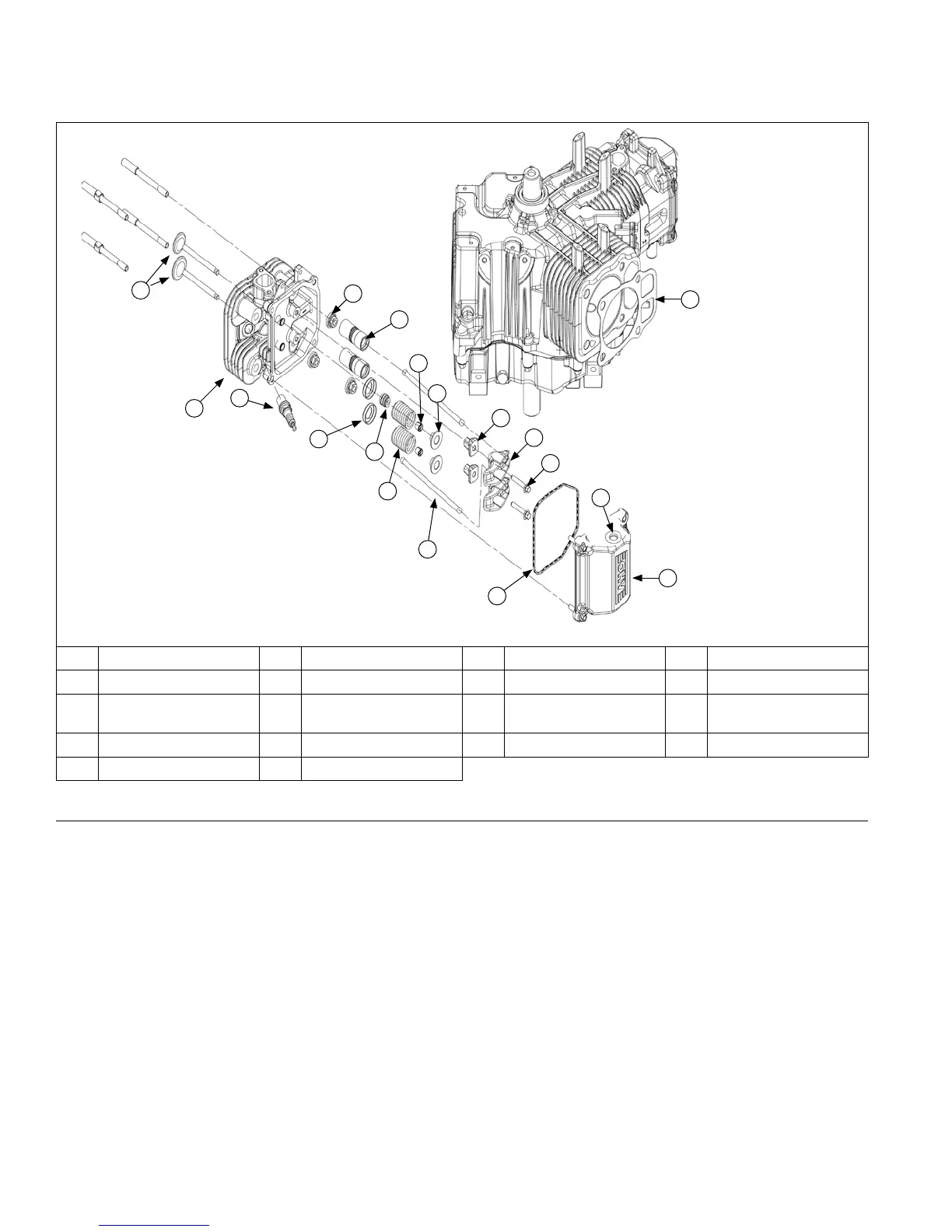
Cylinder Head Components
A Valves B Cylinder Head C Spark Plug D Nut
E Hydraulic Lifter F Cap G Valve Stem Seal H Valve Spring Keeper
I Valve Spring J
Valve Spring
Retainer
K Rocker Arm Pivot L Push Rod
M Rocker Arm N Screw O Valve Cover O-ring P Grommet
Q Valve Cover R Gasket
Remove Cylinder Heads and Hydraulic Lifters
NOTE: Cylinder heads are retained using either screws or nuts and washers on studs. Do not interchange or mix
components, as cylinder heads may have different machining, unique to each fastening method.
1. Remove screws or nuts and washers securing each cylinder head. Unless screws are damaged or questionable,
they can be reused. Discard nuts and washers once removed; do not reuse. Studs (if present) should only be
removed if damaged or if cylinder reconditioning is necessary. Once removed, they must be replaced.
2. Mark location of push rods as either intake or exhaust and cylinder 1 or 2. Push rods should always be reinstalled
in same positions.
3. Carefully remove push rods, cylinder heads, and head gaskets.
4. Remove lifters from lifter bores. Use a hydraulic lifter tool. Do not use a magnet to remove lifters. Mark lifters by
location, as either intake or exhaust, and cylinder 1 or 2. Hydraulic lifters should always be reinstalled in same
position.
D
E
Q
K
L
H
B
C
G
F
A
I
J
M
N
O
P
R
Disassembly/Inspection and Service
62
24 690 07 Rev. HKohlerEngines.com
 Loading...