EasyManua.ls Logo

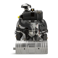
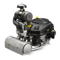
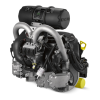
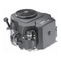
Kohler Command Pro EFI ECH940 User Manual

Kohler Command Pro EFI ECH940
104 pages
To Next Page IconTo Next Page
Page #1 background image
ECH940 & ECH980
Service Manual
KohlerEngines.com
IMPORTANT: Read all safety precautions and instructions carefully before operating equipment. Refer to operating
instruction of equipment that this engine powers.
Ensure engine is stopped and level before performing any maintenance or service.
62 690 13 Rev. A 1
2 Safety
3 Maintenance
5 Specifi cations
21 Tools and Aids
24 Troubleshooting
28 Air Cleaner/Intake
29 Electronic Fuel Injection (EFI) System
53 Governor System
55 Lubrication System
57 Electrical System
63 Starter System
65 Disassembly/Inspection and Service
82 Reassembly

Questions and Answers:

Kohler Command Pro EFI ECH940 Specifications

General IconGeneral
BrandKohler
ModelCommand Pro EFI ECH940
CategoryEngine
LanguageEnglish

Summary

Safety

Safety Precautions

General safety warnings and precautions for engine operation and maintenance.

Maintenance

Maintenance Instructions

Instructions and warnings for performing maintenance procedures safely.

Maintenance Schedule

Schedule of required maintenance tasks based on operating hours.

Repairs/Service Parts

Information on obtaining genuine Kohler service parts and authorized dealers.

Oil Recommendations

Recommended oil types and viscosity based on air temperature.

Fuel Recommendations

Requirements for approved unleaded gasoline, including octane and alcohol content.

Storage

Procedure for storing the engine for extended periods (2 months or more).

Specifications

Engine Dimensions (Heavy-Duty Air Cleaner - Flywheel Side)

Diagram and measurements of engine dimensions with heavy-duty air cleaner.

Engine Dimensions (Heavy-Duty Air Cleaner - PTO Side)

Diagram and measurements of engine dimensions with heavy-duty air cleaner.

Engine Dimensions (Heavy-Duty Air Cleaner - Starter Side)

Diagram and measurements of engine dimensions with heavy-duty air cleaner.

Engine Dimensions (Heavy-Duty Air Cleaner - Opposite Starter Side)

Diagram and measurements of engine dimensions with heavy-duty air cleaner.

Engine Dimensions (Low-Profile Air Cleaner - Flywheel Side)

Diagram and measurements of engine dimensions with low-profile air cleaner.

Engine Dimensions (Low-Profile Air Cleaner - PTO Side)

Diagram and measurements of engine dimensions with low-profile air cleaner.

Engine Dimensions (Low-Profile Air Cleaner - Starter Side)

Diagram and measurements of engine dimensions with low-profile air cleaner.

Engine Dimensions (Low-Profile Air Cleaner - Opposite Starter Side)

Diagram and measurements of engine dimensions with low-profile air cleaner.

Engine Identification Numbers

Information on identifying engine model, specification, and serial numbers.

General Specifications

Key engine specifications such as bore, stroke, displacement, and oil capacity.

Torque Sequences

Diagrams illustrating the correct sequence for tightening fasteners.

Torque Specifications

Specific torque values for various engine components and fasteners.

Clearance Specifications

Permissible clearances and wear limits for engine internal components.

General Torque Values

Torque recommendations for standard metric and English fasteners.

Tools and Aids

Separate Tool Suppliers

Contact information for suppliers of specialized tools.

Tools

List of specific tools required for engine service with part numbers.

Flywheel Holding Tool

Instructions for making a flywheel holding tool.

Rocker Arm/Crankshaft Tool

Instructions for making a tool to lift rocker arms or turn the crankshaft.

Troubleshooting

Troubleshooting Guide

General guide to diagnosing common EFI engine problems by symptom.

External Engine Inspection

Procedure for inspecting the engine's external condition before disassembly.

Cleaning Engine

Guidelines and warnings for cleaning engine components.

Crankcase Vacuum Test

Method and procedure for testing crankcase vacuum using a manometer or gauge.

Compression Test

Procedure for performing a compression test on the engine.

Cylinder Leakdown Test

Alternative test to determine if valves or rings are leaking by pressurizing the cylinder.

Air Cleaner/Intake

Air Cleaner Components (Low-Profile)

Description and service for low-profile air cleaner components.

Air Cleaner Components (Heavy-Duty)

Description and service for heavy-duty air cleaner components.

Breather Tube

Ensuring proper connection of the breather tube.

Air Cooling

Importance of proper cooling and cleaning for preventing overheating.

EFI System

EFI System Overview and Components

Introduction to the EFI system and its major components.

ECU Functions and Key Sensors

Explanation of ECU's role and key sensors like Crankshaft Position and Throttle Position.

EFI System Sensors Explained

Details on Manifold Absolute Pressure (MAP) and Oxygen sensors.

EFI System Notes and Adjustments

Important notes on servicing EFI system components and adjusting idle speed.

ECU Pinout and Wiring Diagram

Diagram and pin assignments for the ECU connectors and wiring harness.

ECU Reset and TPS Learn Procedure

Steps for resetting the ECU and performing the Throttle Position Sensor learn procedure.

Sensor Testing Procedures

Procedures for testing various EFI sensors like Crankshaft Position and TPS.

Fuel Injectors and Ignition Coil Testing

Methods to check fuel injectors and ignition coils for proper operation.

Fuel Pump Module (FPM) Testing

Procedure for testing the fuel pump module for proper operation and pressure.

Troubleshooting Common EFI Issues

Common causes and solutions for EFI issues like starting, stalling, and low power.

Function Test and Fault Codes

Performing a function test and understanding EFI fault codes.

Diagnostic Code Summary

Detailed explanations of specific diagnostic fault codes.

EFI Troubleshooting Flow Chart and Aids

Flow chart and aids to assist in diagnosing EFI system problems.

EFI Diagnostic Flow Diagram

A step-by-step diagnostic flow diagram for EFI system issues.

Governor System

Governor Components

Diagram identifying the various components of the governor system.

Governor Adjustments

Notes and procedures for adjusting the governor settings.

Initial Adjustment Procedure

Steps for performing the initial adjustment of the governor arm.

Lubrication System

Lubrication Components

Diagram identifying the lubrication system components.

Oil Recommendations

Refer to Maintenance section for oil recommendations.

Check Oil Level

Procedure for checking the engine oil level.

Change Oil and Filter

Step-by-step instructions for changing the engine oil and filter.

Oil Cooler

Procedure for cleaning the oil cooler fins.

Oil Sentry™ (if equipped)

Information about the Oil Sentry™ switch and its function.

Electrical System

Spark Plugs

Details on spark plug components, specifications, inspection, and service.

Battery

Information on battery requirements, size recommendations, maintenance, and testing.

Fuses

Information on fuse types, ratings, and replacement procedures.

Test Ignition Systems

Procedures for testing the ignition system and diagnosing problems.

Test for Spark

Method for testing spark on one or both cylinders.

Wire Diagram (8-pin Connector and Key Switch Auxiliary Harness)

Diagram showing wiring connections for the 8-pin connector and key switch.

Battery Charging System

Guidelines for avoiding damage to the electrical system and components.

20/25 Amp Regulated Charging System

Information on the charging system, stator, and rectifier-regulator.

20/25 Amp Battery Charging Systems Testing

Procedures for testing the charging system for proper battery charging.

Starter System

Troubleshooting - Starting Difficulties

Common starting problems and their possible causes and conclusions.

Solenoid Shift Starters - Inspection

Inspection points for the starter drive pinion and clutch mechanism.

Solenoid Tests

Procedures and conclusions for testing the starter solenoid.

Disassembly/Inspection and Service

External Engine Components

Diagram identifying external engine components for disassembly.

Disconnect Spark Plug Leads

Procedure for safely disconnecting spark plug leads.

Drain Oil and Remove Oil Filter

Steps for draining engine oil and removing the oil filter.

Remove Muffler

Procedure for removing the engine muffler.

Remove Cylinder Shrouds and Blower Housing

Steps for removing the cylinder shrouds and blower housing.

Remove Electric Starter Motor

Procedure for removing the electric starter motor.

Remove Control Panel

Steps for removing the control panel.

Remove Air Cleaner Assembly

Procedure for removing the air cleaner assembly.

Remove Control Bracket and Governor Springs

Steps for removing the control bracket and governor springs.

Remove #1 Valley Baffle

Procedure for removing the #1 valley baffle.

Remove #2 Valley Baffle

Procedure for removing the #2 valley baffle.

Remove Oil Sentry™

Procedure for removing the Oil Sentry™ switch.

Remove Oil Cooler

Steps for removing the oil cooler.

Disconnect Fuel Lines

Procedure for safely disconnecting fuel lines from the fuel pump module.

Remove Throttle Body

Procedure for removing the throttle body.

Remove Fuel Injectors

Steps for removing the fuel injectors from the intake manifold.

Remove Intake Manifold/Injectors/Fuel Rail/FPM Assembly

Steps for removing the intake manifold and related components.

Remove Crankshaft Position Sensor

Procedure for removing the crankshaft position sensor.

Remove Oil Filter Housing

Steps for removing the oil filter housing assembly.

Remove Debris Screen and Fan (Option #1)

Procedure for removing the debris screen and fan assembly.

Remove Debris Screen and Fan (Option #2)

Alternative procedure for removing the debris screen and fan assembly.

Remove Flywheel

Steps for removing the flywheel, backing shroud, and baffle components.

Inspection (Flywheel)

Inspecting the flywheel for cracks, keyway damage, and ring gear condition.

Remove Stator and Rectifier-Regulator

Steps for removing the stator and rectifier-regulator assembly.

Remove Fuses

Procedure for removing the fuses.

Remove Barrel Baffles

Steps for removing the barrel baffles, including ignition coils.

Remove Backing Shroud and Wiring Harness

Procedure for removing the backing shroud and wiring harness assembly.

Cylinder Head Components

Diagram identifying cylinder head components.

Remove Spark Plugs

Procedure for removing spark plugs.

Remove Valve Covers and Fuel Pump

Steps for removing valve covers and fuel pump.

Remove Cylinder Heads and Hydraulic Lifters

Steps for removing cylinder heads and hydraulic lifters.

Disassemble Cylinder Heads

Procedure for disassembling the cylinder heads, including valve components.

Valve Details

Diagram and specifications for intake and exhaust valves.

Breather/Closure Plate/Oil Reservoir Components

Diagram identifying breather, closure plate, and oil reservoir components.

Recondition Valve Seat Inserts

Instructions for reconditioning valve seat inserts.

Lapping Valves

Procedure for lapping valves to ensure proper fit.

Valve Stem Seals

Note on always using new valve stem seals.

Remove Breather Assembly

Steps for removing the breather assembly.

Remove Oil Reservoir and Pickup Screen

Procedure for removing the oil reservoir and pickup screen.

Remove Closure Plate Assembly

Steps for removing the closure plate assembly.

Oil Pump Assembly (Disassembly and Inspection)

Steps for disassembling and inspecting the oil pump.

Install Closure Plate Crankshaft Bearing (PTO) and Oil Seal

Procedure for installing the crankshaft bearing and oil seal.

Crankcase Components

Diagram identifying crankcase components for reassembly.

Oil Seal Details

Diagram and procedure for installing the oil seal.

Remove Camshaft

Procedure for removing the camshaft and inspection.

Remove Connecting Rods with Pistons and Rings

Steps for removing connecting rods, pistons, and rings.

Piston and Rings (Inspection)

Inspection of pistons and rings for wear or damage.

Install New Piston Rings

Instructions for correctly installing new piston rings.

Remove Crankshaft

Procedure for removing the crankshaft from the crankcase.

Crankshaft Components and Details (Inspection)

Inspection of crankshaft components like gear teeth and bearing surfaces.

Remove Governor Yoke, Cross Shaft, and Seal

Steps for removing the governor yoke, cross shaft, and seal.

Remove Lifter Feed Chamber Cover and Gasket

Procedure for removing the lifter feed chamber cover.

Remove Flywheel End Oil Seal

Steps for removing the flywheel end oil seal.

Remove Crankshaft Bearing (flywheel)

Procedure for removing the crankshaft bearing if replacement is needed.

Crankcase (Inspection and Service)

Inspection of crankcase for gasket surfaces, cylinder bore scoring, and resizing.

Honing (Cylinder Bore)

Procedure and specifications for honing the cylinder bore.

Clean Cylinder Bore After Honing

Critical steps for cleaning the cylinder bore after machining.

Measuring Piston-to-Bore Clearance

Procedure for accurately measuring piston-to-bore clearance.

Reassembly

Crankcase Components

Diagram identifying crankcase components for reassembly.

Install Governor Shafts, Seal, and Governor Gear

Steps for installing governor shafts, seal, and governor gear.

Governor Components and Details

Diagram illustrating governor components and their installation.

Install Crankshaft

Procedure for installing the crankshaft into the crankcase.

Install Connecting Rods with Pistons and Rings

Steps for installing connecting rods, pistons, and rings.

Install Camshaft

Procedure for installing the camshaft, including timing marks.

Determining Camshaft End Play

Method for checking and adjusting camshaft end play.

Oil Pump Assembly

Steps for installing the oil pump assembly.

Install Closure Plate Assembly

Procedure for installing the closure plate assembly.

Install Oil Pickup Screen

Steps for installing the oil pickup screen.

Install Oil Reservoir

Procedure for installing the oil reservoir with torque sequence.

Check Crankshaft End Play

How to check crankshaft end play using a dial indicator.

Install Breather Assembly

Steps for installing the breather assembly and filter.

Install Engine (oil) Temperature Sensor

Procedure for installing the engine oil temperature sensor.

Install Hydraulic Lifters

Procedure for installing hydraulic lifters in their correct positions.

Install Cylinder Heads

Steps for installing the cylinder heads, including torque sequence.

Install Push Rods and Rocker Arms

Procedure for installing push rods and rocker arms.

Install Valve Covers

Steps for installing the valve covers.

Install Spark Plugs

Procedure for installing spark plugs, including gap check and torque.

Install Oil Filter Housing Assembly

Steps for reassembling the oil filter housing.

Install Backing Shroud

Procedure for installing the backing shroud assembly.

Install Barrel Baffles

Steps for installing the barrel baffles.

Install Stator

Procedure for installing the stator.

Install Rectifier-Regulator

Steps for installing the rectifier-regulator.

Install Wiring Harness

Procedure for installing the wiring harness.

Install Flywheel

Steps for safely installing the flywheel onto the crankshaft.

Install Crankshaft Position Sensor

Procedure for installing the crankshaft position sensor.

Install Debris Screen and Fan (Option #1)

Reassembly sequence for debris screen and fan (Option #1).

Install Debris Screen and Fan (Option #2)

Reassembly sequence for debris screen and fan (Option #2).

Install Intake Manifold

Steps for installing the intake manifold with torque sequence.

Install Fuel Injectors

Procedure for installing fuel injectors, including O-rings and clips.

Install Fuel Pump Module (FPM)

Steps for installing the fuel pump module and related components.

Install #2 Valley Baffle

Procedure for installing the #2 valley baffle.

Install #1 Valley Baffle

Procedure for installing the #1 valley baffle.

Install Throttle Body

Steps for installing the throttle body, linkage, and sensor.

Install Governor Lever

Procedure for installing and adjusting the governor lever.

Install Fuel Lines to Fuel Pump

Procedure for installing fuel lines to the fuel pump.

Install Control Bracket and Air Cleaner Assembly

Steps for installing the control bracket and air cleaner assembly.

Install Oil Sentry™ (if equipped)

Procedure for installing the Oil Sentry™ switch.

Install Oil Cooler

Steps for installing the oil cooler.

Install Blower Housing and Cylinder Shrouds

Procedure for installing the blower housing and cylinder shrouds.

Install Electric Starter Motor

Steps for installing the electric starter motor.

Install and Adjust Governor Lever

Procedure for installing and adjusting the governor lever.

Install Control Panel (if equipped)

Steps for installing the control panel.

Install Muffler

Procedure for installing the muffler.

Install Oil Filter and Add Oil to Crankcase

Steps for installing the oil filter and adding oil to the crankcase.

Prepare Engine for Operation

Pre-operation checks and procedures after engine reassembly.

Testing Engine and Setting Speed

Procedure for testing the engine and setting idle and high speeds.

Related product manuals