82E-5 – 98E-5 SERIES 7-3
7. FUEL INJECTION PUMP/GOVERNOR
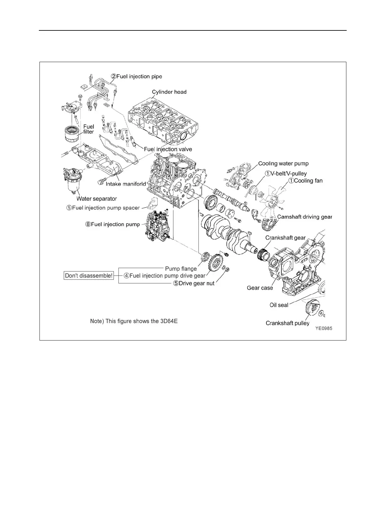
7.2.2 External view and components
7.2.3 Disassembly procedure
Disassembly from the engine body
1) Remove the cooling fan, pulley and V-belt.
2) Remove the fuel injection pipe, fuel oil piping, fuel return pipe and rear stay. See point 1 of 7.2.5.
3) Remove the fuel injection pump cover (the cover of the drive gear).
4) Make ID marks on the gearing part of the pump drive gear and the idle gear with paint and so on.
See Point 2 of 7.2.5.
5) Loosen a fuel injection pump drive gear nut, and remove a pump drive gear from the fuel injection pump by
using a gear puller. See Point 3 of 4.3.4.
6) Remove a drive gear nut carefully not to drop it to the inside of the gear case.
7) Record the installation angle of the fuel injection pump precisely by using a mark-off line and a sticker.
See (4) of 2.2.7.
8) Remove the fuel injection pump. See Point 3 of 7.2.5.

 Loading...
