140-3 SERIES
13-5
DISASSEMBLY AND ASSEMBLY SPECIAL TOOL LIST
SPECIAL TOOL LIST
★ Tools with part number 79 x T- xxx - xxxx cannot be supplied (they must be locally manufactured).
★ Necessity: ■ ...........Cannot be substituted, should always be installed (used)
● ...........Extremely useful if available, can be substituted with commercially available part
★ New/Remodel: N............Tools with new part numbers, newly developed for this model
R............Tools with upgraded part numbers, remodeled from items already available for oth-
er models
Blank .....Tools already available for other models, used without any modification
★ Tools marked in the Sketch column are tools introduced in the sketches of the special tools (See SKETCH-
ES OF SPECIAL TOOLS).
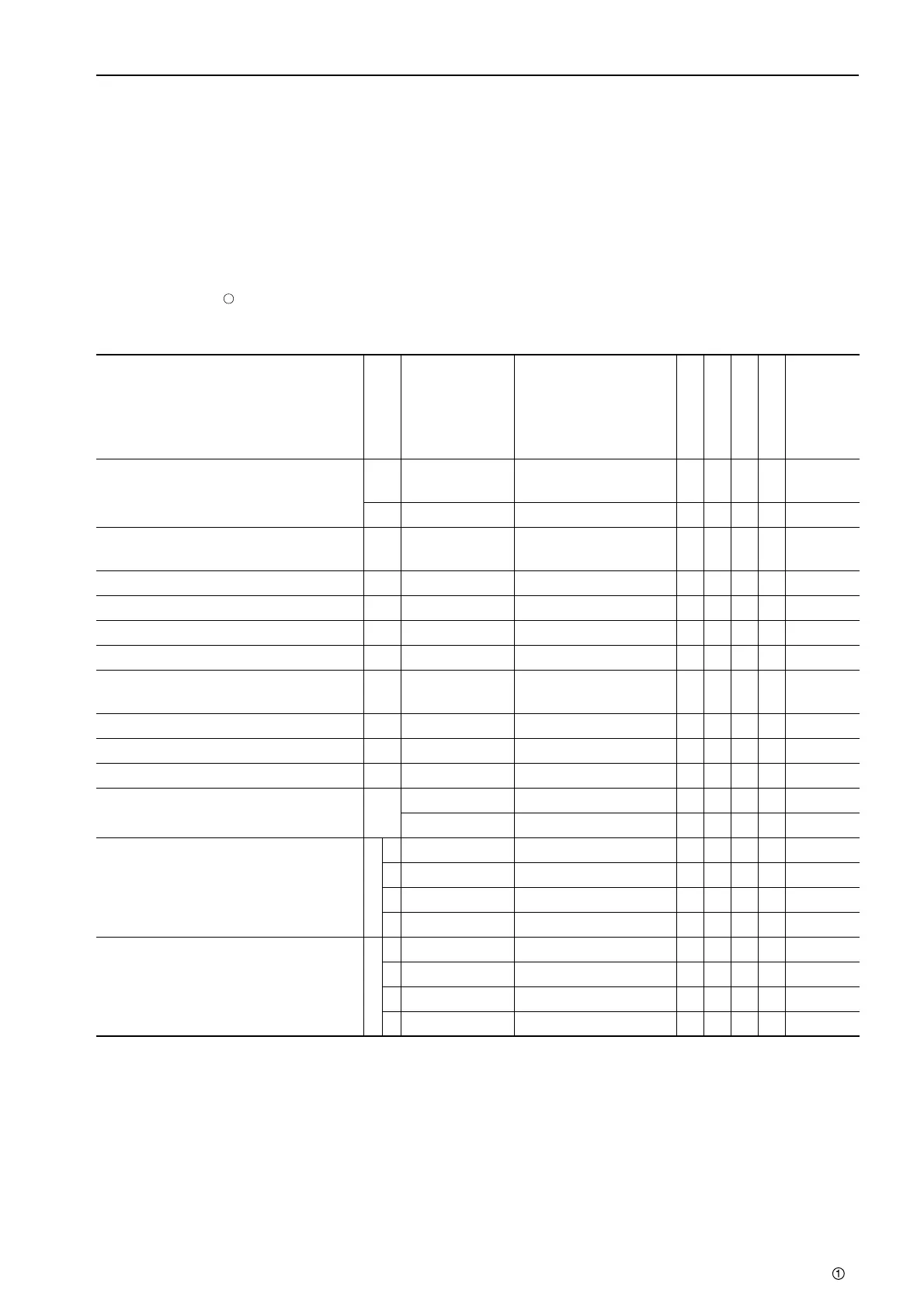
Component
Symbol
Part No. Part Name
Necessity
Q'ty
New/Remodel
Sketch
Nature of
work,
remarks
Disassembly, assembly of engine
assembly
A 790-901-1260
Adapter
(To be installed to B)
■ 1
B 790-501-2001 Engine overhaul stand ■ 1
Removal, installation of cylinder head
valve spring
C 795-102-2102 Spring pusher ■ 1
Removal, installation of piston ring D 795-100-1191 Piston ring tool ■ 1
Removal of cylinder liner E 795-236-1000 Liner puller ■ 1
Press fitting of cylinder liner F 795-230-5472 Liner driver ■ 1
Insertion of piston assembly G 795-236-1500 Piston holder ■ 1
Measurement of projection of
cylinder liner
H 795-502-1121 Gauge holder ■ 1
Adjustment of valve clearance I 795-125-1210 Filler gauge ● 1
Angular tightening of bolt J 790-331-1110 Wrench ● 1
Pulling rear seal out of engine L 795-931-1100 Seal puller ● 1
Press fitting of front seal M
795-521-1110 Push tool ■ 1
01050-31640 Bolt ■ 3
Press fitting of engine rear seal N
1 795-931-1210 Sleeve jig ■ 1
2 795-931-1220 Sleeve jig ■ 1
3 01050-31645 Bolt ■ 3
4 01050-31625 Bolt ■ 3
Removal of fuel supply pump O
1 795-471-1320 Plate ■ 1N
2 01017-32020 Bolt ■ 1N
3 01010-81095 Bolt ■ 2N
4 01643-31032 Washer ■ 2N
 Loading...

