15-12
140-3 SERIES
TESTING AND ADJUSTING CYLINDER BLOCK
REPLACING CAM BUSHING
Special tools
1. Removal of cam bushing
When replacing the cam bushing, first re-
move the blind plug at the rear of the cylinder
block.
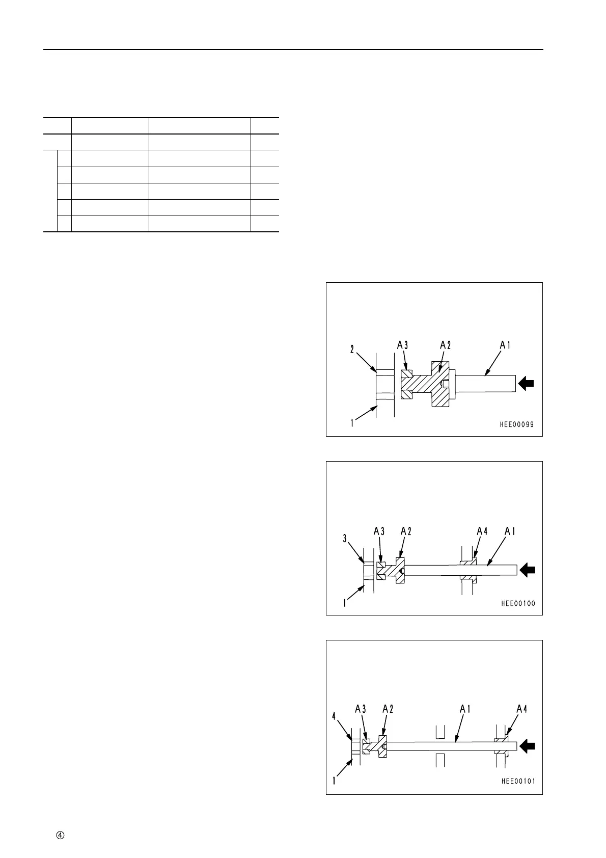
1) Removal of No. 1, 7 bushings
As shown in the diagram, assemble push
tool A2, collar A3, and push bar A1 of push
tools A, then hit the push bar to knock bush-
ing (2) out from cylinder block (1).
2) Removal of No. 2, 6 bushings
Assemble push bar A1, push tool A2, collar
A3, and guide A4 of push tool A, then hit the
push bar to knock bushing (3) out from cylin-
der block (1).
3) Removal of No. 3, 4, 5 bushings
Assemble push bar A1, push tool A2, collar
A3, and guide A4 of push tool A, then hit the
push bar to knock bushing (4) out from cylin-
der block (1).
No. Part No. Part Name Q’ty
A 795-213-1200 Push tool 1
A
1 795-213-1250 Push bar 1
2 795-213-1210 Push tool 1
3 795-213-1240 Collar 1
4 795-213-1230 Guide 1
5 792-103-0400 Grip 1
 Loading...

