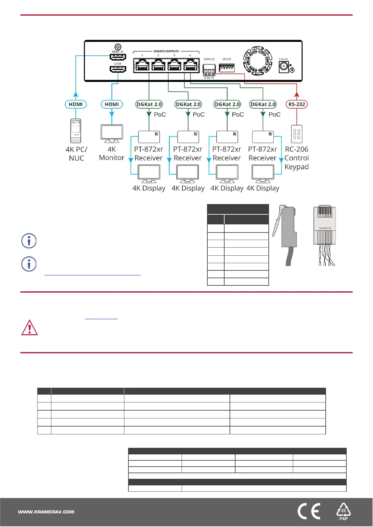
Step 4: Connect inputs and outputs
Always switch OFF the power on each device before connecting it to your VM-4DKT.
Wiring the RJ-45 Connectors
This section defines the DGKAT pinout, using a straight pin-to-pin cable
with RJ-45 connectors.
The ground shielding must be connected/soldered to the
connector shield.
To achieve specified extension distances, use the
recommended Kramer cables available at
www.kramerav.com/product/VM-4DKT.
Using third-party cables may cause damage!
Step 5: Connect power
Connect the power adapter to the VM-4DKT and then plug it into the mains electricity.
Safety Instructions (See www.kramerav.com for updated safety information)
Caution:
• For products with relay terminals and GPI\O ports, please refer to the permitted rating for an external connection, located next to the terminal or in the User Manual.
• There are no operator serviceable parts inside the unit.
Warning:
• Use only the power cord that is supplied with the unit.
• Disconnect the power and unplug the unit from the wall before installing.
Step 6: Operate VM-4DKT
Set the VM-4DKT DIP-switches:
A DIP-switch that is down is on, up is off. Changes to the DIP-switches take effect immediately.
ON (down) – Default EDID (default)
OFF (up) – Auto-acquire enabled (default)
ON (down) – Auto-acquire disabled
OFF (up) – Active (default)
OFF (up) – Standard (default)
OFF (up) – Normal operation mode (default)
ON (down) – Firmware upgrade mode.
Operate remotely, by RS-232 serial
commands transmitted by PC, or
other serial controller.
RS-232 Control / Protocol 3000
Example (get device model name): #model?<cr>
Factory Default Parameters
 Loading...