82410 • 82710 • 82910 WSM, 12271
11790F10530
SERVICING
(1)
Cylinder
Head and Valves
00000F10010
1 ENGINE
Main
Bearing
Case
Assembly
1.
Remove the two main bearing case screws
1,
and remove the
main bearing case assembly, being careful with the thrust
bearing and crankshaft bearing
2.
2.
Remove the main bearing case assembly
1,
2 and 3 as above.
(When
reassembling)
• Clean the oil passage in the main bearing case.
• Apply clean engine oil on the bearings.
• Install the main bearing case assemblies
in
the original positions.
Since diameters of main bearing case vary, install them
in
order
of makings
[A,
B, C] from the gear case side.
• Match the alignment numbers (1) on the main bearing case.
• When installing the main bearing case
1,
2,
and
3,
face the mark
"FLYWHEEL"
to the flywheel.
• Install the thrust bearing with its oil groove facing outward.
• Confirm that the main bearing case moves smoothly after
tightening the main bearing case screw 1 to the specified torque.
29.4 to 34.3 N·m
Tightening torque Main bearing case screw 1
3.0 to 3.5 kgf·m
21.7 to 25.3 ft-Ibs
(1) Alignment Number
12270810400
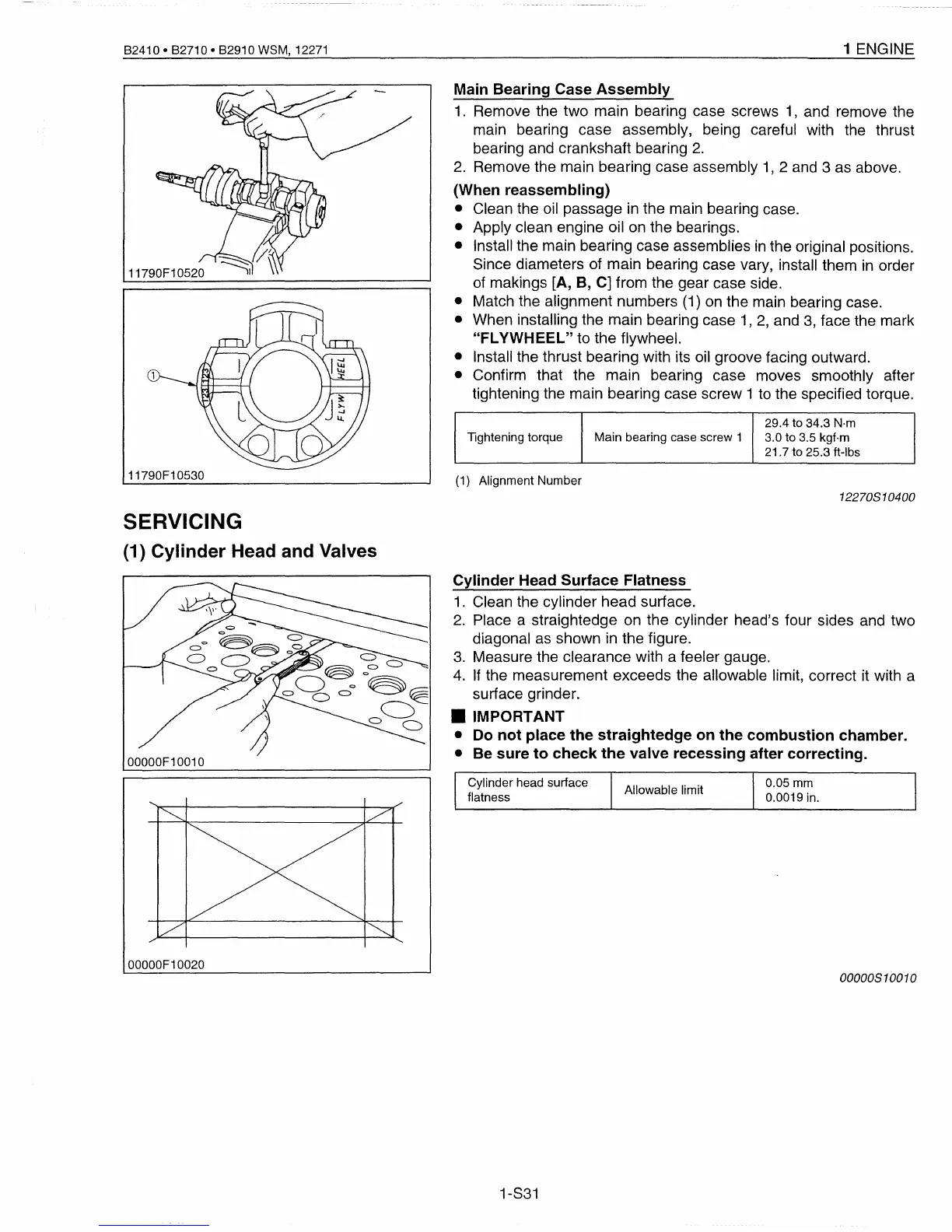
Cylinder
Head
Surface
Flatness
1.
Clean the cylinder head surface.
2.
Place a straightedge on the cylinder head's four sides and two
diagonal as shown in the figure.
3.
Measure the clearance with a feeler gauge.
4.
If
the measurement exceeds the allowable limit, correct it with a
surface grinder.
• IMPORTANT
• Do
not
place
the
straightedge
on
the
combustion
chamber.
• Be
sure
to
check
the
valve
recessing
after
correcting.
00000F10020
Cylinder head surface
flatness
1-S31
Allowable limit
0.05 mm
0.0019 in.
00000810010
 Loading...


