6.4 Installing crankshaft (for 3
cylinders)
NOTE
• Measure the
side clearance of crankshaft when
you assemble again.
• This topic is used for only 3 cylinders engine
(D1803-CR-E4, -TE4, -TIE4).
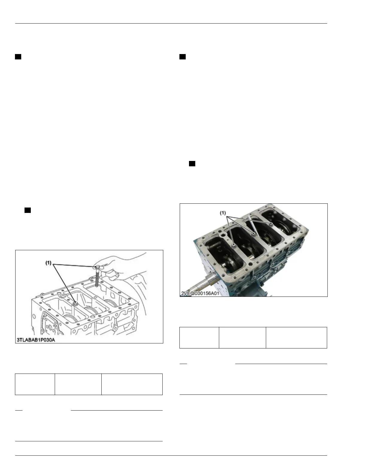
1. Install the crankshaft until the crankpin of the first
cylinder comes to the center of the third cylinder
.
2. Turn the crankshaft by 2.09 rad (120°)
counterclockwise to set the crankpin of the second
cylinder to the bottom dead center.
3. Install the crankshaft until the crankpin of the
second cylinder comes to the center of the third
cylinder.
4. Turn the crankshaft to set the crankpin of the third
cylinder to the bottom dead center.
5. Install the crankshaft completely.
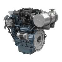
6. Align the screw hole of the main bearing case with
the screw hole of the crankcase.
7. Install the main bearing case screw 2 (1) by hand.
NOTE
• Apply oil to the main bearing case screw 2.
•
If you cannot turn the screw 2 smoothly,
align the screw holes between the crankcase
and the main bearing case correctly.
(1) Main bearing case screw 2
8. Tighten the main bearing case screw 2 (1) to
specified torque.
T
ightening tor-
que
Main bearing case
screw 2 (1)
68.6 to 73.5 N⋅m
7.00 to 7.49 kgf⋅m
50.6 to 54.2 lbf⋅ft
RELATED PAGE
4.30 Measuring angular deviation between crankshaft
T.D.C. and crankshaft position sensor detected T
.D.C.
on page 4-112
6.5 Installing crankshaft (for 4
cylinders)
NOTE
• Measure the
side clearance of crankshaft when
you assemble again.
• This topic is used for only 4 cylinders engine
(V2403-CR-E4, -TE4, -TE4BG, -TIE4).
1. Hold the crankpins to the horizontal directions (right
or
left) and install the crankshaft completely into
crankcase.
2. Turn the crankshaft to set the crankpin of the fourth
cylinder to the horizontal directions (right or left).
3. Align the screw hole of the main bearing case with
the screw hole of the crankcase.
4. Install the main bearing case screw 2 (1) by hand.
NOTE
• Apply oil to the main bearing case screw 2.
•
If you cannot turn the screw 2 smoothly,
align the screw holes between the crankcase
and the main bearing case correctly.
(1) Main bearing case screw 2
5. Tighten the main bearing case screw 2 (1) to
specified torque.
T
ightening tor-
que
Main bearing case
screw 2 (1)
68.6 to 73.5 N⋅m
7.00 to 7.49 kgf⋅m
50.6 to 54.2 lbf⋅ft
RELATED PAGE
4.30 Measuring angular deviation between crankshaft
T.D.C. and crankshaft position sensor detected T
.D.C.
on page 4-112
4. ENGINE
SERVICING
6. Assembling
D1803-CR-E4,D1803-CR-TE4,D1803-CR-TIE4,V2403-CR-E4,V2403-CR-TE4,V2403-CR-TE4BG,V2403-CR-TIE4
 Loading...


