2-S20
GL6000, GL7000, GL9000, GL11000, WSM
GENERATOR
[3] SERVICING
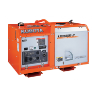
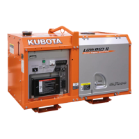
(1) Terminal Voltage for Each Part During Normal Periods (No-load Periods)
Output Terminal
1. With the NFB in the ON position, measure the voltage in each
phase and each line.
2. If the factory specification is not indicated, inspect the output
circuit or the wiring harness.
(Refer to "5. WIRING DIAGRAM” (2-M8).)
W1068933
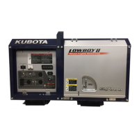
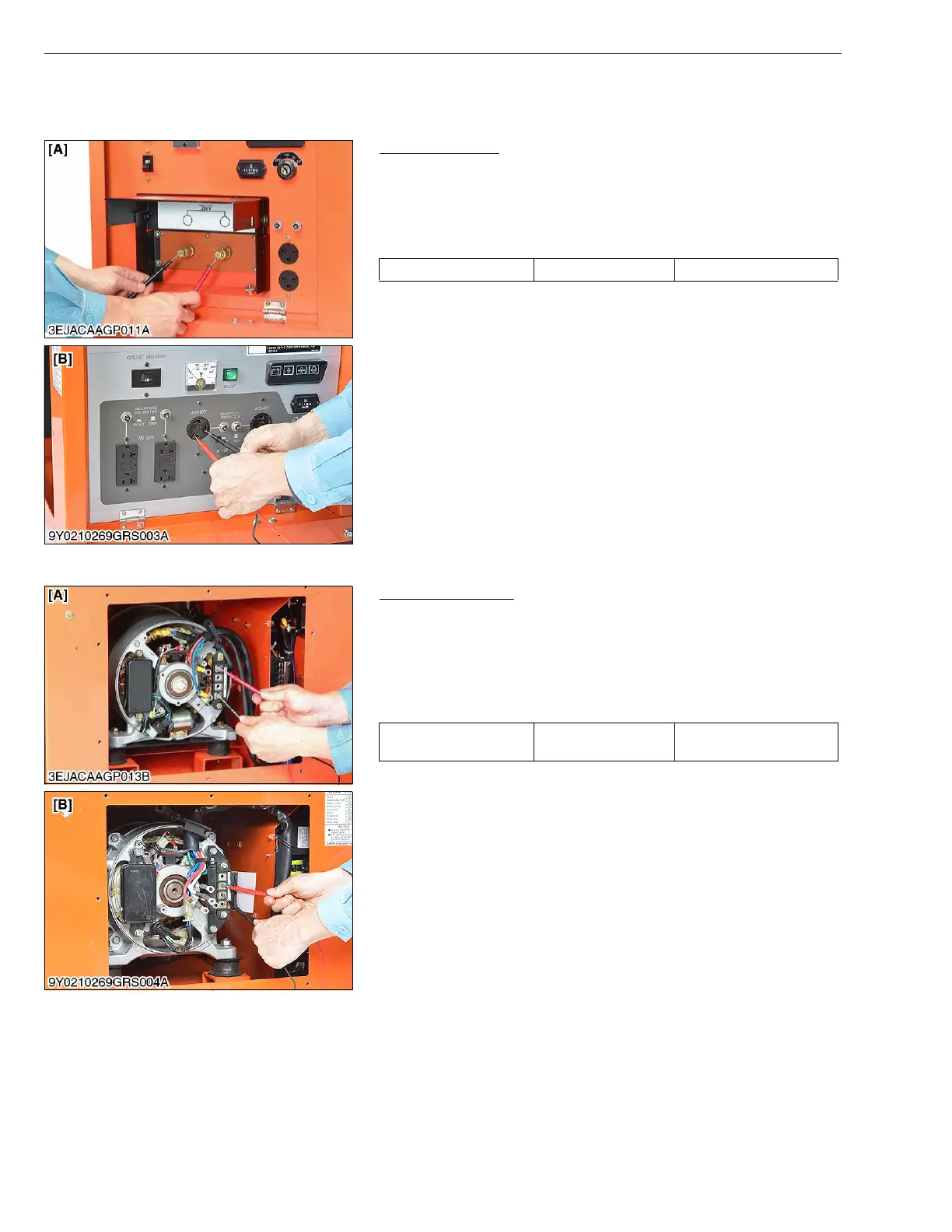
(2) Stator Coil
Main Coil Winding
1. Test for continuity between coil leads with a milliohm meter.
Many kind of wiring have been arranged in the stator depending
on the voltage variation.
2. If the resistance is not as specified, replace the stator or contact
service station.
(Refer to "5. WIRING DIAGRAM” (2-M8).)
* Measurement is not possible with a regular tester.
W1026118
Output voltage Factory spec. Rated voltage 7 or 8 %
[A] Terminal Type [B] Receptacle Type
Resistance Factory spec.
Refer to "2. SERVICING
SPECIFICATION” (2-S6).
[A] G6000, GL7000 [B] GL9000, GL11000
 Loading...