LTR-5 INSTRUCTIONS FOR USE
Thank you for having chosen a LAE electronic product. Before installing the instrument, please read these instructions carefully
to ensure maximum performance and safety.
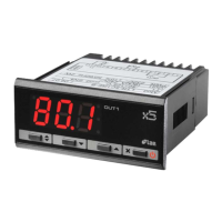
DESCRIPTION INDICATIONS
Thermostat output
Fig.1 — Front panel
Setpoint button. Increase button.
Decrease button. Exit / Stand-by button.
INSTALLATION
Insert the controller through a hole measuring 71x29 mm.
Make sure that electrical connections comp ly w i th the paragraph “wiring diagrams”. To reduce the e ffec ts of elec troma gne tic
disturbance, keep the sensor and signal cables well separate from the power wires.
Fix the controller to the panel by means of the suitable clips, by pressingly gently; if fi tted, check that the rubber gasket
adheres to the panel perfectly, in order to prevent debris and moisture infi ltration to the back of the instrument.
Place the probe T1 inside the room in a point that truly represents the temperature of the stored product.
OPERATION
DISPLAY
During normal operation, the display shows either the temperature measured or one of the following indications:
OFF
Controller in stand-by
E1
In tuning: timeout1 error
OR
Probe T1 overrange or failure
E2
In tuning: timeout2 error
TUN / 5.4
Controller in autotuning
E3
In tuning: overrange error
SETPOINT (display and modifi cation of desired temperature value)
press button
for at least half second, to display the setpoint value.
By keeping button
pressed, use button
or
to set the desired value (adjustment is within the minimum SPL and the
maximum SPH limit).
When button
is released, the new value is stored.
STAND-BY
Button
, when pressed for 3 seconds, allows the controller to be put on a standby or output control to be resumed (with
SB=YES only).
CONTROLLER AUTOTUNING IN PID MODE
Before starting
Adjust the setpoint 1SP to the desired value.
Set 1Y=PID.
Make sure that the 1PB value matches the desired control mode (1PB<0 for heating; 1PB>0 for refrigeration).
Start autotuning
Keep buttons
+
pressed for 3 seconds. 1CT blinks on the display.
With +
or
set the cycle time in order to defi ne the dynamic of the process to be controlled.
To start autotuning press
+
or wait for 30 seconds. To abort the autotuning function, press
X
.
During autotuning
During the entire autotuning phase, the display alternates
with the actual temperature measured.
In case of power failure, when power is resumed, after the initial autotest phase, the controller resumes the autotuning
function.
To abort the autotuning, without modifying the previous control parameters, keep button
X
pressed for 3 seconds.
After the autotuning has taken place successfully, the controller updates the control parameters and start to control.
Errors
If the autotuning function failed, the display shows an error code:
E1 timeout1 error: the controller could not bring the temperature within the proportional band. Increase 1SP in case of
heating control, vice versa, decrease 1SP in case of refrigerating control and re-start the process.
E2 timeout2 error: the autotuning has not ended within the maximum time allowed (1000 cycle times). Re-start the autotuning
process and set a longer cycle time 1CT.
E3 temperature overrange: check that the error was not caused by a probe malfunction, then decrease 1SP in case of heating
control, vice versa increase 1SP in case of refrigerating control and then re-start the process.
To eliminate the error indication and return to the normal mode, press button
X
.
Control improvement
To reduce overshoot, reduce the integral action reset 1AR.
To increase the response speed of the system, reduce the proportional band 1PB. Caution: doing this makes the system less
stable.
To reduce swings in steady-state temperature, increase the integral action time 1IT; system stability is thus increased,
although its response speed is decreased.
To increase the speed of response to the variations in temperature, increase the derivative action time 1DT. Caution: a high
value makes the system sensitive to small variations and it may be a source of instability.
RECALIBRATION
Have a precision reference thermometer or a calibrator to hand.
Ensure that OS1=0 and SIM=0.
Switch the controller off then on again.
During the auto-test phase, press buttons
X
+
, and keep them pressed till the controller shows 0AD.
With buttons
and
select 0AD or SAD: 0AD allows a calibration of 0, inserting a constant correction over the whole
scale of measurement. SAD allows a calibration of the top part of the measurement scale with a proportional correction
between the calibration point and 0.
Press to display the value and then use
+
or
to make the read value coincide with the value measured by the
reference instrument.
Exit from calibration by pressing button
X
.
CONFIGURATION PARAMETERS
Setup menu is accessed by pressing buttons +
X
for 5 seconds.
With button
or
select the parameter to be modifi ed.
Press button
to display the value.
By keeping button
pressed, use button
or
to set the desired value.
When button
is released, the newly programmed value is stored and the following parameter is displayed.
To exit from the setup, press button
X
or wait for 30 seconds.
PAR
RANGE DESCRIPTION
SCL
1°C;
2°C;
°F
Readout scale.
1°C : measuring range -50/-19.9 … 99.9 /150°C for LTR-5T
-40/-19.9 … 99.9/125°C for LTR-5C
0.0 … 99.9 % r.H. for LTR-5A
2°C : measuring range -50 … 150°C for LTR-5T
-40 … 125°C for LTR-5C
00 … 99 %r.H. for LTR-5A
°F : measuring range -60 … 300°F for LTR-5T
-40 … 250°F for LT R-5C
Caution : upo n changin g the SCL va lue, it is t hen abs olu tel y neces sar y to r e-con fig ure t he pa ramet ers re levan t to t he
absolute and relative temperatures ( SPL, SPH, 1SP, 1HY, etc..) .
SPL
-50..SPH Minimum limit for 1SP setting
SPH
SPL .150° Maximum limit for 1SP setting
1SP
SPL ... SPH Setpoint (value to be maintained in the room).
1Y
HY / PID Control mode.
With 1Y=HY you select control with hysteresis: parameters 1HY and 1CT are used.
With 1Y=PID you select a Proportional-Integral-Derivative control mode: parameters 1PB, 1I T, 1DT, 1AR, 1C T will
be used.
1HY
-19.9…19.9°C Thermostat differential [control with hysteresis].
Set 1HY on a value greater than zero to make the output work in refrigerating mode, vice versa set on a value lower
than zero to make the output work in heating mode. With 1HY= 0 the output is always off.
OFF
ON
1SP 1SP+1HY
T[°]
OFF
ON
1SP1SP-1HY
T[°]
Fig. 1a. ON /OFF refrigerating control (1Y=HY, 1HY>0) Fig. 1b. ON/OFF heating control (1Y=HY, 1HY<0)
1PB
-19.9…19.9°C Proportional band [PID control ] .
Set 1PB on a value greater than zero to make the output work
in refrigerating mode, vice versa set on a value lower than
zero to make the output work in heating mode. With 1PB=0
the output is always off.
With a proportional controller, the temperature is controlled
by var ying the t ime of activation of the output. The nearer the
temperature to set point, the less time of activation. A small
proportional band increases the promptness of response
of the system to temperature variations, but tends to make
it less stable. A purely propor tional control stabilises the
temp eratur e withi n the propor tional band but does n ot cancel
the deviation from the set point.
1IT
0…999s Integral action time [PID control].
The steady-state error is cancelled by inserting an
integral action into the control system. The integral action
time, determines the speed with which the steady-state
temperature is achieved, but a high speed (1IT low) may be
the cause of overshoot and instability in the response. With
1IT= 0 the integral control is disabled.
1DT
0…999s Derivative action time [PID control].
Response over shoot in a system cont rolled by a Propor tional-
Deri vativ e contro ller may be re duced by inserting a deriva tive
action in the control. A high derivative action (1DT high)
makes the system very sensitive to small temperature
variations and causes instability. With 1DT=0 the derivative
control is disabled.
1AR
0…100% Reset of integral action time referred to 1PB [PID control].
Decreasing the parameter 1AR reduces the integral control action zone, and consequent ly the overshoot (see figure
on paragraph 1IT).
1CT
0…255s Cycle time.
In the ON/OFF control (1Y= HY) , after the output has switched on or off, it will remain in the new state for a minimum
time of 1CT seconds, regardless of the temperature value.
In the PID control (1Y=PID) , the cycle time is the period of time in which the output completes a cycle (Time ON +
Time OFF). The faster the system to be controlled reacts to temperature changes, the smaller the cycle time should
be, in order to obtain a greater temperature stability and less sensitivity to load variations.
1PF
ON / OFF Output state in case of probe failure.
BAU
NON / SBY With BAU=SBY, the stand-by button is enabled.
SIM
0...100 Display slowdown.
OS1
-12.5..12.5°C Probe T1 offset.
ADR
1...255 LTR-5 address for PC communication.
WIRING DIAGRAMS
TECHNICAL DATA
Power supply
LTR-5…D 12Vac/dc±10%, 2W
LTR-5…E 230Vac±10% , 50/60Hz, 2W
LTR-5…U 115Vac±10%, 50/60Hz, 2W
Relay outputs (LTR-5..R..)
LTR-5.SR.. OUT1 16(4)A
LTR-5.QR.. OUT1 12(4)A
SSR drive (LTR-5..F..)
OUT1 15mA 12Vdc
Inputs
LTR-5A…: 0-1V
LTR-5C…: NTC 10K Ω@25°C, part No. L AE SN4...
LTR-5T…: PTC 1000Ω@25°C, part No. L AE ST1…
Measuring Range
LTR-5A…: 0…99%r.H.
LTR-5C…: -40…125°C
LTR-5T…: -50…150 °C
Measuring accuracy
LTR-5A…: <±0.7%r.H. in the measuring range
LTR-5C…: <±0.3°C -40…100°C; ±1°C out of that range
LTR-5T…: <±0.3°C -50…140°C; ±1°C out of that range
Operating conditions
-10 … + 50°C; 15…80% r.H.
CE (Reference Norms)
EN60730-1; EN60730-2-9;
EN5 5022 (Class B) ;
EN50082-1
Front protection
IP55
VIA PADOVA, 25
31046 ODERZO /TV /ITALY
TEL. +39 - 0422 815320
FAX +39 - 0422 814073
www.lae-electronic.com
E-mail: sales@lae-electronic.com
PARTNER VENEZIA • 041 5460713
6 7
OUT1
12(4)A
2
3
4
9 10
11
rH
V
VINV+ V-
TTL
230V~
data I/O
LTR-5AQRE-A
RS485
2
3
4
6 7
OUT1
16(4)A
10
11
230V~
data I/O
LTR-5TSRE-B
1SP
1PB
Temperature
Overshoot
Steady-state error
Process
temperature
Time
1SP
1PB
Temperature
Overshoot
Process
temperature
Time
1PBx1AR%
integral control
action area
1SP
1PB
Temperature
Overshoot
Process
temperature
Time
RS485
6 7
OUT1
S.S.R.
+
-
15mA
4
12V
3
10
11
230V ~
data I/O
LTR-5CSFE-B
ISTR LTR-5 INGL/TED.indd 1ISTR LTR-5 INGL/TED.indd 1 11-12-2007 15:45:2711-12-2007 15:45:27