Step 4: Pinging Devices
1. From the main DeviceInstaller window, select the
installed device from the list, then click the Ping
Device icon
. A reply from the selected device
indicates an active device. An error message indicates
a problem with the network. See the user manual for
troubleshooting network problems.
2. From the Ping Device window, you can ping devices
not listed in the main window by entering a new
address in the IP address field.
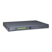
DSTni-XPress DR-IAP devices allow you to install a
protocol such as MODBUS Bridge for your automation
application. Skip Step 5 if you have a DSTni-XPress DR..
Step 5: Upgrade the Firmware
1. Click the Upgrade Firmware icon
. The
Upgrade Firmware window displays. The IP address
displays in the first field.
2. Select the current protocol using the list button in the
Existing Firmware field. (factory default = IAP
Standard Tunnel)
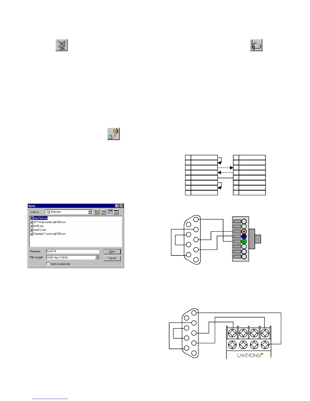
3. Click the open file icon next to the FW File field. A
list of firmware files displays. Use the search buttons
to locate the firmware files on the CD or downloaded
files from the Lantronix support web page.
4. Select the desired protocol and click Open. The
selected file and path displays in the FW File field.
5. Click Upgrade FW File. The File upgrade successful
message displays. Click OK and close the upgrade
firmware window.
Step 6: Configure the Device
To view or update the Device Server configuration, use the
Device Management window to open a Telnet connection.
1. Click the Device Management icon
. Click the
Telnet to Device icon.
2. When the Telnet window opens, you have 5 seconds to
press the Enter key.
3. Note the firmware code and description on the first few
lines.
4. Review and edit the settings to match your application.
When done, enter S to save the changes and Q to Quit.
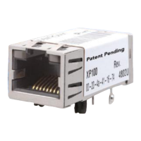
Step 7: Connecting Serial Devices
The cable below is a typical PC (COM1) to DSTni-XPress
DR cable using the serial RJ-45 connector. You can use the
serial port to configure and test the port settings prior to
connection to your automation device.
DTR (Out)
RXD (In)
TXD (Out)
Signal Ground
CTS (In)
RTS (Out)
DSR (In)
4
6
3
2
5
7
8
SERIAL RJ-45DTE, 9-Pin, FEMALE
No Connection
DTR (Out)
RXD (In)
TXD (Out)
Signal Ground
CTS (In)
RTS (Out)
No Connection
3
2
1
4
5
6
7
8
7
4
3
2
1
5
9
8
6
CTS
RTS
DTR
DSR
GND
TXD
RXD
5
4
3
1
8
SERIAL RJ-45DTE, 9-Pin, FEMALE
View from
Connector End
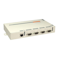
The following cable connects a typical PC (COM1) to the
DSTni-XPress DR through the serial screw terminals.
4
3
2
1
5
9
8
7
6
CTS
RTS
DTR
DSR
GND
TXD
RXD
RXD
TXD
GND
DTE, 9-PIN, FEMALE DTE, 9-PIN, FEMALE
 Loading...