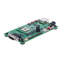
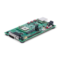
Ref Des. Connector/Header Functions
JP4
SDIO Master/Slave Select
Install Jumper pins 1 to 2 for SDIO Master Mode
Install Jumper pins 2 to 3 for SDIO Slave Mode
JP5
USB Host Power Out Jumper
Install to provide power out for USB host mode. Do not install for device mode
(default)
JP6
USB Host Power Out Jumper
Install to provide power out for USB host mode. Do not install for device mode
(default)
J1
JTAG Pads
Install JTAG pogo pin header at J1. Use Tag-Connect TC2050-IDC cable probe
and TC2050-ARM2010 adapter for JTAG connections
J2
IO pin header
Header for connection to module power, serial port, and configurable pin
connections.
J3 Ethernet RJ45
J4
5V Barrel Connector
Input port for 5V board power
J6 DB9 RS232 Serial Port
J7 Edge connector socket for xPico 240/250 module edge card
J9
Module USB Port
Defaults to USB device port. Jumper options available to run as a host port.
 Loading...