J7
Pin
LED Ref
Design
Color LED Function
None LED4 Blue
3.3V Power LED
LED is ON when evaluation board 3.3V power is up.
J2HeaderPins
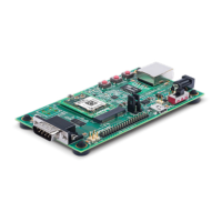
The J2 Pin Header table lists the pin functionality of the additional evaluation kit
headers. Included is the J7 connection to the xPico 200 edge module connector.
J2PinHeader
J7 module
pin
J2 Header
Pin
Signal Function
Secondary
Function
N/A 2,4,6 VIN
Evaluation board
5V power
1,7,18,33,
9,45,51,57,
63,69,75
1,3,5,33,
35,37,39
Ground
Evaluation board
Ground
2,4,72,74 34,36,38,40 3V3(M)
Evaluaton board
3.3V power
Routes to J7 module
pins via R1
50 7 CP1 Configurable pin 1
USB host mode over-
current flag input
48 9 CP2/INT Configurable pin 2
SPI interrupt input
USB host mode port
power enable output
46 11 CP3 Configurable pin 3 SPI-MISO

 Loading...