Important Safety Instruction
Accessory Checklist
Copyright Information
Disclaimer of Warranties and Limitation of Liabilities
Copyright © 2018 by LAUNCH TECH. CO., LTD. All rights reserved. No part of this
publication may be reproduced, stored in a retrieval system, or transmitted in any form or by
any means, electronic, mechanical, photocopying, recording or otherwise, without the prior
written permission of LAUNCH.
All information, specifications and illustrations in this publication are based on the latest
information available at the time of printing. Launch reserves the right to make changes at
any time without prior notice.
Safety Instructions
Before using this test equipment, please read the following safety information carefully.
Always perform automotive testing in a safe environment.
?
?
?
?
?
?
?
?
?
?
?
Wear an ANSI-approved eye shield when testing or repairing vehicles.
The vehicle shall be tested in a well-ventilated work area, as engines produce various
poisonous compounds (hydrocarbon, carbon monoxide, nitrogen oxides, etc.)
Do not connect or disconnect any test equipment while the ignition is on or the engine is
running.
Put blocks in front of the drive wheels and never leave the vehicle unattended while
testing.
Do not drive the vehicle and operate the test equipment at the same time. Any distraction
may cause an accident.
Keep clothing, hair, hands, tools, test equipment, etc. away from all moving or hot engine
parts.
Keep a fire extinguisher suitable for chemical, gasoline and electrical fires nearby.
Before starting the engine, put the gear lever in NEUTRAL (for manual transmission) or
PARK (for automatic transmission) to avoid injury.
To avoid damaging the test equipment or generating false data, please make sure the
vehicle battery is fully charged and the connection to the vehicle DLC (Data Link
Connector) is clear and secure.
Automotive batteries contain sulfuric acid that is harmful to skin. In operation, direct
contact with the automotive batteries should be avoided. Keep the ignition sources away
from the battery at all times.
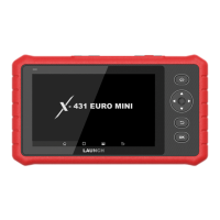
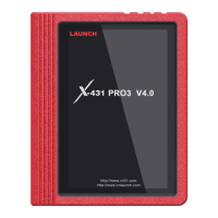
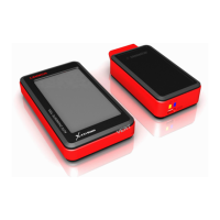
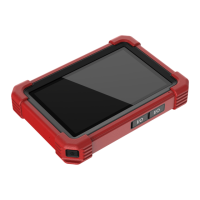
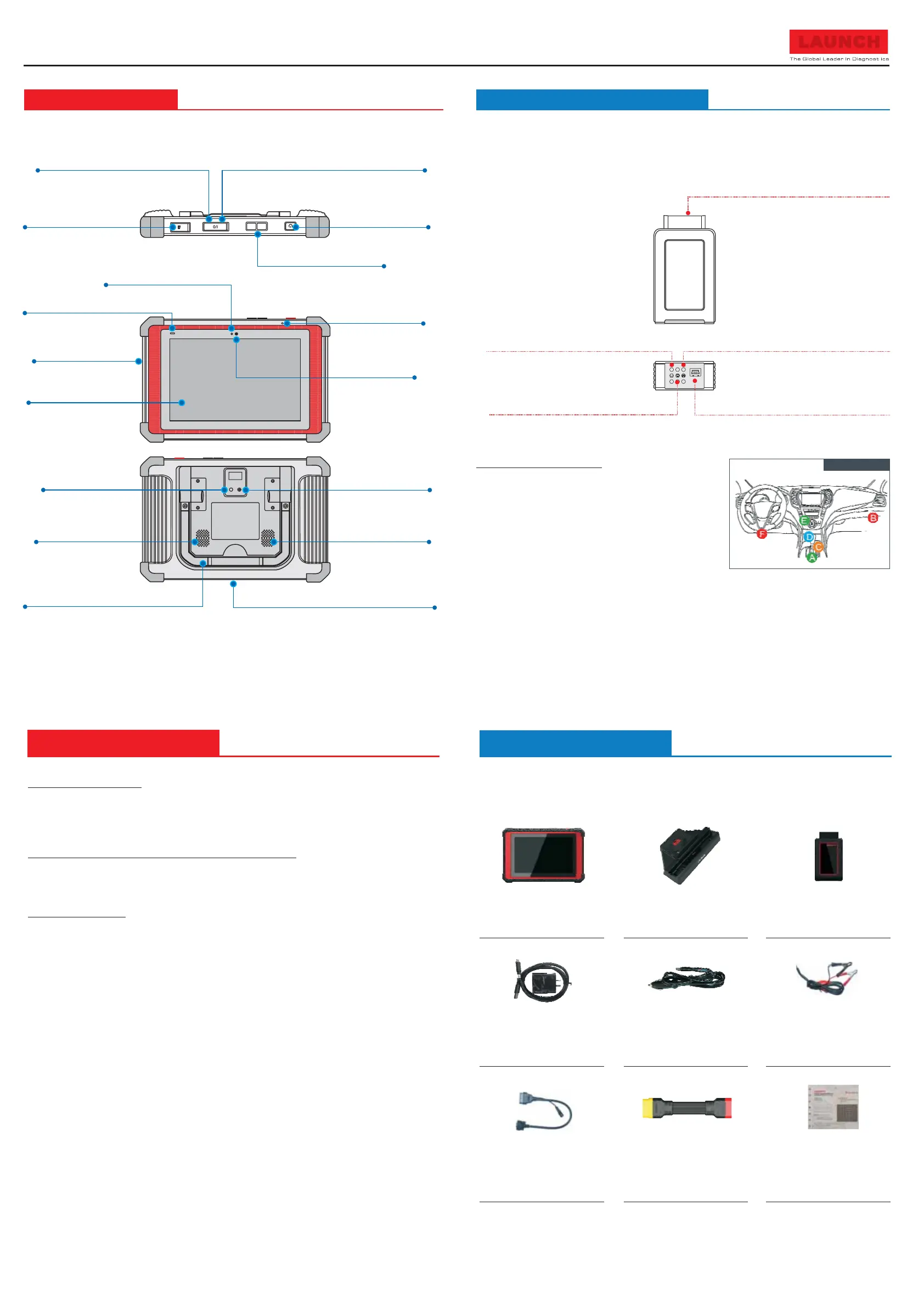
X-431 Throttle Handset
A tablet for showing
test results.
Docking Station
For charging & docking the
handset.
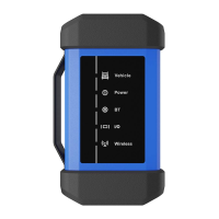
VCI Device
A device for accessing
vehicle data.
Power Adaptor
To supply power to the tablet
through connection to AC
outlet.
OBD I Adaptor Cable
A converting cable for
connecting non-16 pin
connector.
Cigarette Lighter Cable
To supply power to the non-
16pin connector via vehicle’s
cigarette lighter receptacle.
Battery Clamps Cable
To provide power to the non-
16pin connector through
connection to the vehicle’s
battery.
Private & Confidential Paper
A piece of paper bearing
Product S/N and Verification
Code, which is required for
your VCI activation.
OBDII Extension Cable
To connect the VCI device
for extension purpose.
For different product configurations, the accessories may vary. For detailed accessory
items, please consult from the local agency or check the packing list supplied with X-431
Throttle together.
DLC Location
Note: Remember to remove the VCI
connector from the vehicle’s DLC if
it keeps unused.
Power indicator
(It lights up while the VCI connector
is plugged into the vehicle's DLC.)
(By default, it is in wireless communication mode
when the VCI is powered up and illuminates blue.)
(To connect on vehicle's OBD II DLC.)
OBD-16 connector
ECU communication indicator
(It flashes when the VCI connector is
communicating with the vehicle.)
Data transmission port
Only reserved for future use.()
Wireless (BT) communication indicator
Install the VCI connector
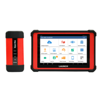
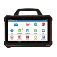
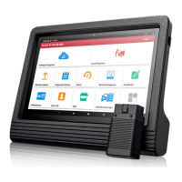
X-431 Throttle Handset VCI (Vehicle Communication Interface)
The handset acts as the central processing system, which is used to receive and analyze the
live vehicle data from the VCI connector and then output the test result.
The VCI connector works as a vehicle communication interface device, which is used to
connect to the vehicle's DLC (Data Link Connector) socket directly or via OBD II extension
cable to read the vehicle data and then send it to the handset via wireless (BT)
communication. It only works with the vehicle with 12V battery voltage.
1. Locate vehicle’s DLC socket: The DLC (Data Link
Connector) is typically a 16-pin connector where
diagnostic code readers interface with the vehicle's
on-board computer.
It is usually located on driver’s
side, about 12 inches away from the center of
dashboard. See Figure DLC Location.
In case no DLC is found, please refer to Automobile
Repair Manual.
2.
Plug the VCI connector into the vehicle's DLC (It is suggested to use the OBD II extension
cable to connect the DLC and the VCI). Normally the power indicator of the VCI will light
up.
Quick Start Guide
X-431 Throttle
LAUNCH
+
-
Type-C Charging Port
Charging Slot
Data Transmission Port
Memory Card Slot
Ambient Light Sensor
Charging Indicator
(Red means Charging, and
Green means Fully Charged.)
Microphone
Microphone
Front Camera
Power/Screen
Lock Button
Volume Buttons
10.1" Touch Screen
Camera Flash
Rear Camera
Audio Speaker
Adjustable Kickstand
Audio Speaker
(Reserved for and
other USB devices use only.)
add-on modules,
Reserved for charging or transferring data.()
(
)
To store the memory card
for storage extension.
)
(For charging the handset via
placing it on the docking station
(
)
Flip out it to any angle and work comfortable
at your desk, or hang it on automotive part.
Learn more about diagnostic and testing tools we have.
 Loading...