301 Fulling Mill Road, Suite G
Middletown, PA 17057
Phone (800) 321-2343 / Fax (717) 702-2546
www.onqlegrand.com
Page 1 of 3
INSTRUCTION/INSTALLATION SHEET
Selective Call Intercom Video Door
Unit
IS-0426 REV. O
©Copyright 2008 by On-Q/Legrand All Rights Reserved.
1. Introduction
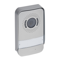
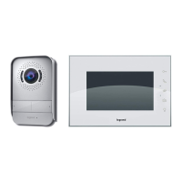
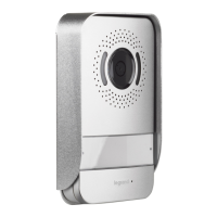
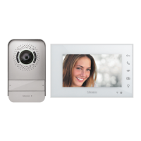
The On-Q /Legrand Selective Call Intercom Video Door Unit, PN IC5003-XX
(see Figure 1), is a weather resistant door unit that allows a visitor to notify
the occupants of their presence by pushing the door chime button. The
occupants can then see who is at the door via the optional On-Q LCD
Console and associated module, initiate two-way communications with the
visitor and optionally open the door (requires separate door release device).
The Door Unit is available in white (-WH), shiny brass (-SB), antique brass (-
AB), brushed stainless (-BS) and oil-rubbed bronze (-OB).
2. Description
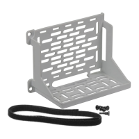
The Video Door Unit is a 2-gang product that mounts within a two-gang
electrical box (56” from the floor to the bottom of the box). There is also a
two-gang surface-mount box available (P/N IC5006-BK) for unique or
retrofit installation requirements.
3. Installation
Installation of the Selective Call Video Door Unit is best accomplished at multiple times during new
construction, at “Rough-in” before the drywall and siding is installed, and at “Trim-out” after the drywall is
installed.
A. “Rough-in” steps:
1. Run a Cat 5 cable from the Enclosure where the Selective Call Intercom Module will be installed to the
2 gang box at the Video Door Unit location.
NOTE: A single Video Door Unit in a one Module system may be run up to 650 feet from the Module to
support a gate application. All other Door Units on the system must be within 330 feet (100 meters) of
the Distribution Module.
NOTE: It is important to keep all Category 5e cable runs, regardless of use, at least 12 inches away from
AC electrical cables. If it proves necessary to cross an existing AC cable, do so only at a 90 degree
angle.
B. “Trim-out” steps:
NOTE: All terminations can be correctly completed by following the T568A pin assignments. It is
important that you accurately terminate using T568A at all locations. All terminations on the Selective Call
Intercom System utilize RJ45 jacks. Refer to Figure 2 for correct T568A termination for RJ45 plugs.
RJ-45
Pin
1 – White/Green
2 – Green
3 – White Orange
4 – Blue
5 – White/Blue
6 – Orange
7 – White/Brown
8 – Brown
RJ-45
Pin
1 – White/Green
2 – Green
3 – White Orange
4 – Blue
5 – White/Blue
6 – Orange
7 – White/Brown
8 – Brown
Figure 1
Figure 2