2
LNX74-543.3
Carel pGD1 Digital Display/Interface Module
MOUNTING
HOLES
RJ12 CABLE
CONNECTION
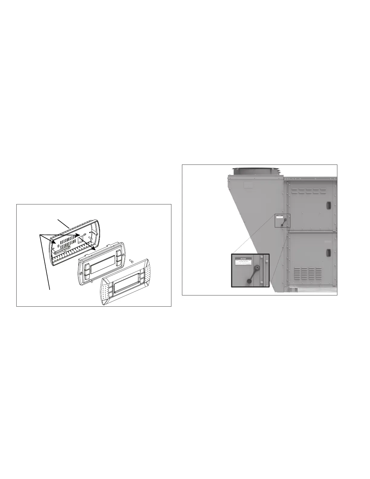
Figure 2.1 – Exploded View of pGD1 Interface Module
2. Attach the back to a standard 2” x 4” electrical box mounted
sideways. Use the round-head screws supplied through
the mounting holes on the back of the interface module as
shown in Figure 2.1.
3. Connect one end of an RJ12 cable (not to exceed 100 feet
in length) to the back connection on the pGD1 (see Figure
2.2). For the connection at the unit mounted controller,
refer to the section "Wiring Connection at Unit Controller".
Note: If the distance between the pGD1 and the Carel
controller exceeds 100 feet, refer to the appropriate Carel
literature for further information.
4. Attach the pGD1 controller to the back that was mounted
in Step 2 using the flush-head screws supplied in the
packaging and then install the front trim plate.
5. Proceed to section "Wiring Connection at Unit Controller".
Handheld Installation
For handheld use of the pGD1 interface, follow the steps below,
otherwise proceed to the section "Wall Installation".
1. If the pGD1 interface is to be used as a hand-held device,
connect one end of an RJ12 cable (not to exceed 100 feet
in length) to the back connection on the pGD1 (see Figure
2.1). For the connection at the unit mounted controller, refer
to the section "Wiring Connection at Unit Controller".
Note: If the distance between the pGD1 and the Carel
controller exceeds 100 feet, refer to the appropriate Carel
literature for further information.
2. Proceed to section "Wiring Connection at Unit Controller".
Wall Installation
For wall mounting of the pGD1 interface, follow the steps below,
otherwise proceed to the section "Handheld Installation".
1. If the pGD1 interface is to be used as a hand-held device,
remove the back of the interface module and front trim plate
as shown in Figure 2.1.
Figure 2.2 - Optional External Data Port
Wiring Connection at Unit Controller
The wiring of the pGD1 interface to the unit must be within 100
feet. If the distance exceeds 100 feet, refer to the appropriate
Carel literature for further information.
The wiring of the pGD1 interface to the unit controller varies by
unit model and configuration as follows:
• Direct to Unit Controller: The RJ12 cable is to be
connected to the J10 connection on the unit mounted
controller. Applies to all units.
• Units with External Data Port Option: Some units are
equipped with an external data port option on the exterior
of the cabinet as shown in Figure 2.2. The RJ12 cable is to
be connected to the data port connection. Applies only to B
and C-Cabinet units that include the option.

 Loading...
