Page 11
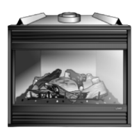
PLACEMENT OF EMBER MATERIAL ON FRONT BURNER
SEPARATE ROCK WOOL INTO PIECES ABOUT THE SIZE OF A NICKEL. KEEP THE PIECES FLUFFED UP, NOT MATTED,
AND PLACE APPROXIMATELY AS SHOWN IN THIS FIGURE.
NOTE - TOO MANY EMBERS ON THE FRONT BURNER WILL CAUSE POOR COMBUSTION.
FIGURE 10
8- Millivolt Wiring (Millivolt Units) -
In applications where the burner switch is to be unit-
mounted in the field -
Install the switch in the gas valve mounted bracket
and wire according to figure 37.
In applications where the burner switch is to be wall-
mounted -
Install a field-provided handy box in a convenient
location adjacent to the appliance. Install the ON/OFF
switch and faceplate and wire according to figure 37.
In thermostat applications -
Install the thermostat in a suitable location and wire
accordingtofigure37.
9- 24 Volt Wiring (Electronic Ignition Units) -
In applications where the burner switch is to be unit-
mounted in the field -
Install the ON/OFF switch in the gas valve mounted
bracket and wire according to figure 38.
In applications where the burner switch is to be wall-
mounted -
Install a field-provided handy box in a convenient
location adjacent to the appliance. Install ON/OFF
switch and faceplate and wire according to figure 38.
In thermostat applications -
Install the thermostat in a suitable location and wire
accordingtofigurefigure38.
10 - 120 Volt Wiring -
Millivolt Units - 120 volt wiring isrequired on Millivolt
units only when a fan kit is being installed. Wire fan
kitaccordingtofigure37.
ElectronicIgnition Units All electronic ignition units
require 120 volt wiring. Install wiring according to fig-
ure 38.
When 120 volt electrical power is applied, the ap-
pliance must be electrically grounded according to
local codes or, in the absence of local codes, with the
current National Electric Code, ANSI/NFPA No. 70,
in the USA or CSA C22.1 Canadian Electrical Code
in Canada.
11 - Prepare the vent collar for use as indicated in the
venting section. Attach either Lennox flexible or unit-
ized rigid concentric vent to vent collar, at the top
(DT/DTH units) or rear (DR/DRH units), of the ap-
pliance as indicated in the venting section. Vent ter-
minations are indicated in venting section.
12 - Make gas piping connections as indicated in gas pip-
ing section.
WARNING
Do not operate appliance unless glass frame is
properly installed. Glass must not be broken or
cracked. If glass is damaged, replace with ap-
propriate glass/frame assembly available through
Lennoxrepair parts.Substitution of any otherthan
Lennox-specified glass can lead to property dam-
age or personal injury.
13 - Carefully reinstall the glass door. Tighten the three
bolts at the bottom of the door securely.
14 - Install the bustle; in flush-faced model applica-
tions, install the top panel; in louvered-face model
applications, install the louvers.
15 -Remove the eyebrow from its protective wrap-
ping. Slide the eyebrow into the slots on the lower
edges of the radiant panel (flush-faced model ap-
plications) or the lower edges of the cabinet top
(louvered-face model applications).
NOTE - The eyebrow must be used in all applications.
16 - Continue with the procedures indicated in the start-up
and adjustments section.
 Loading...