Page 5
H – Secondary Limit (S21)
The secondary limit switch (S21) is a high temperature
limit located on the left side of the blower scroll. The
limit is a N.C. SPST auto-reset limit connected in series
with the ignition control A3. The switch is similar in de-
sign to the primary limit control. See figure 4. The limit
detects heat in the blower compartment indicating a
possible fan failure. When S21 senses heat, the igni-
tion control immediately stops ignition and closes the
gas valve. If unit is running and heat is detected, the
gas valve will close and ignition control will be dis-
abled. The switch is factory set and cannot be ad-
justed. See table 4. The switch automatically resets.
Series
Series
G20RQ4/5(X)E–125
G20RQ4/5(X)E–150
SECONDARY LIMIT TEMPERATURES
TABLE 4
UNIT MODEL NO. TEMP. RISE TEMP. FALL
G20RQ2/3(X)E–50
G20RQ3(X)E–75
Series
Series
140
°F + 5°F 110°F + 10°F
G20RQ3/4(X)E–100
G20RQ5(X)E–100
Series
Series
G20RQ3(X)E–125
Series
130
°F + 5°F 100°F + 10°F
G20RQ4(X)E–75
Series
120
°F + 5°F90°F + 10°F
130
°F + 5°F 100°F + 10°F
140
°F + 5°F 110°F + 10°F
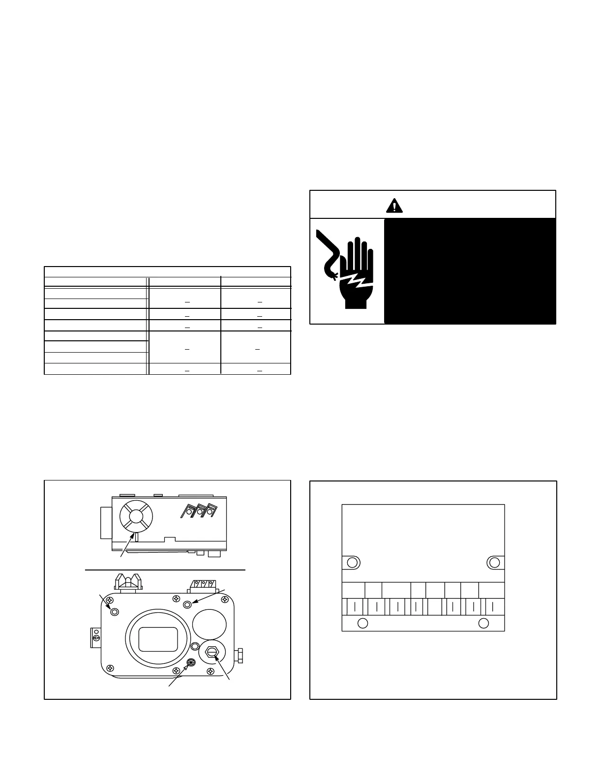
I – Gas Valve (Figure 6)
All G20RE units use a Robertshaw gas valve. All gas
valves are internally redundant to assure safety shut–
off. If the gas valve must be replaced, the same type
valve must be used.
INLET
PRESSURE
TAP
ON
OFF
FIGURE 6
ROBERTSHAW 7100 GAS VALVE
GAS VALVE KNOB SHOWN IN OFF POSITION
PCM
PRESSURE REGULATOR
ADJUSTMENT SCREW
TOP VIEW
FRONT
VIEW
PILOT ADJUSTMENT SCREW
VALVE
INLET
VALVE
OUTLET
OUTLET
PRESSURE
TAP
J – Electronic Ignition Control (Figure 7)
The Robertshaw electronic ignition control (A3) is an
intermittent ignition control module located on the
vestibule panel. See figure 1. When there is a call for
heat, the control generates a spark to ignite the pilot,
after which the control senses the flame. If the flame
current is too weak (less than 1 microamp) the control
will shut down and de–energize the gas valve. Flame
current should be between 1 and 5 microamps.
DANGER
Shock Hazard.
Spark related components con-
tain high voltage. Disconnect
power before servicing unit. The
ignition control is not field repair-
able.
Can cause unsafe operation, inju-
ry or death.
The 24VAC terminals and the gas knob are located on
top of the valve. All terminals on the gas valve are con-
nected to wires from the electronic ignition control.
The left red wire to terminal “P” energizes the pilot
valve. An orange sensing wire from terminal
“V”(marked VALVE SENSE) of the BCC2-2 control rides
“piggy back” on the “P” terminal connection. The
main valve, terminal “M,” is energized by the right red
wire. The blue wire, terminal “C,” is the common for
the gas valve.
ROBERTSHAW IGNITION CONTROL
FIGURE 7
MV/PV – MAIN AND PILOT VALVE COMMON
MV – 24VAC OUTPUT TO MAIN VALVE
PV – 24VAC OUTPUT TO PILOT
TH – 24VAC INPUT FROM BCC2-2 THROUGH LIMITS
SENSE – MICROAMP SIGNAL FROM FLAME SENSOR
TR – 24VAC COMMON
IGN – HIGH VOLTAGE TO SPARK IGNITOR
TRIGN SENSE TH MV MV/PVPV