Page 4
DANGER
Danger of explosion.
There are circumstances in which odorant used with
LP/propane gas can lose its scent. In case of a leak,
LP/propane gas will settle close to the floor and may
be difficult to smell. An LP/propane leak detector
should be installed in all LP applications.
Do not attempt to bleed the gas lines of air. Call your
local gas provider.
Start−Up & Operation Information
WARNING
If you do not follow these instructions exactly, a fire
or explosion may result causing property damage,
personal injury or death.
BEFORE PLACING THE UNIT INTO OPERATION, smell
all around the appliance area for gas. Be sure to smell next
to the floor because some gas is heavier than air and will
settle on the floor.
The gas valve on the G71MPP is equipped with a gas con-
trol switch. Use only your hand to move the control switch.
Never use tools. If the switch will not move by hand, do not
try to repair it. Call a licensed professional service techni-
cian (or equivalent). Force or attempted repair may result in
a fire or explosion.
Placing the G71MPP furnace into operation:
G71MPP units are equipped with a SureLight
®
ignition sys-
tem. Do not
attempt to manually light burners on this fur-
nace. Each time the thermostat calls for heat, the burners
will automatically light. The ignitor does not get hot when
there is no call for heat on units with SureLight
®
ignition
system.
Operating the Gas Valve (Figure 2)
1 − STOP! Read the safety information at the beginning of
this section.
2 − Set the thermostat to the lowest setting.
3 − Turn off all electrical power to the unit.
4 − This furnace is equipped with an ignition device which
automatically lights the burners. Do not try to light the
burners by hand.
5 − Remove the upper access panel.
6 − Move the gas valve switch to the OFF position. See fig-
ure 2.
7 − Wait five minutes to clear out any gas. If you then smell
gas, STOP! Immediately call your gas supplier from a
neighbor’s phone. Follow the gas supplier’s instruc-
tions. If you do not smell gas go to next step.
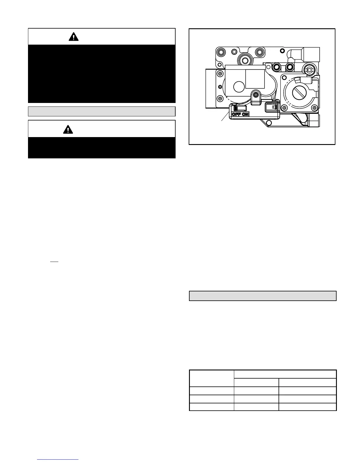
FIGURE 2
VARIABLE CAPACITY GAS VALVE
GAS VALVE SHOWN IN OFF POSITION
GAS VALVE
SWITCH
8 − Move gas valve switch to ON position. See figure 2.
9 − Replace the upper access panel.
10 − Turn on all electrical power to to the unit.
11 − Set the thermostat to desired setting.
NOTE − When unit is initially started, steps 1 through 11
may need to be repeated to purge air from gas line.
12− If the appliance will not operate, follow the section
Turning Off Gas to the Unit" and call your service tech-
nician or gas supplier.
Turning Off Gas to the Unit
1 − Set the thermostat to the lowest setting.
2 − Turn off all electrical power to the unit if service is to be
performed.
3 − Remove the upper access panel.
4 − Move the gas valve switch to the OFF position.
5 − Replace the upper access panel.
Filters
All G71MPP filters are installed external to the unit. Filters
should be inspected monthly. Clean or replace the filters
when necessary to ensure proper furnace operation. Re-
placement filters must be rated for high velocity airflow.
Table 1 lists recommended filter sizes.
A filter must be in place and when the unit is operating. The
filter access panel must also be in place and properly se-
cured during unit operation.
TABLE 1
Furnace
Filter Size