Page 19
FIGURE 19
VENT PLUG
(Must be
glued in
place)
PLUG
PLUG
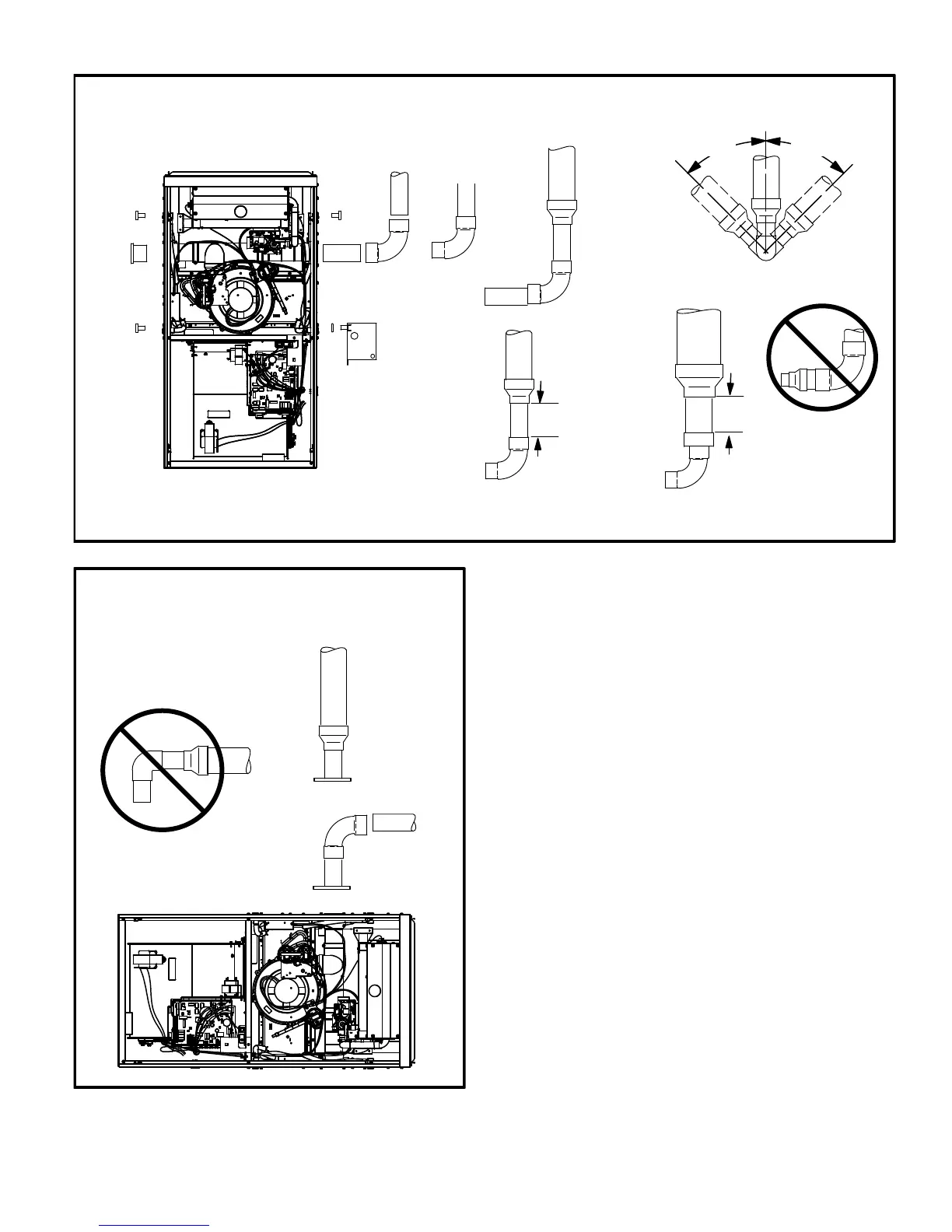
TYPICAL EXHAUST PIPE CONNECTIONS AND CONDENSATE TRAP INSTALLATION
IN UPFLOW OR DOWNFLOW DIRECT VENT APPLICATIONS
(Right−Hand Exit in Upflow Application Shown)
CONDENSATE
TRAP
(Must be installed
on same side as
exhaust piping)
PLUG
*2" diameter street elbow provided.
**Street elbow may be used on −070 and −090
G71MPP−135 with
3" OR 4" vent pipe
3" to 2" REDUCING ELBOW
(provided)
2"
G71MPP−070,
or −090 with
2−1/2", 3", or 4"
vent pipe
2" max
length
TRANSITION
(use only if 4"
pipe is
required)
4"
2"
2−1/2",
3", OR
4"
TRANSITION
2"
2"
G71MPP−110 with
2−1/2", 3", OR 4"
vent pipe
*2"
TRANSITION
2−1/2",
3", OR
4"
2"
2"
or
45°
MAX
45°
MAX
SIDE VIEW
2" max
length
**2"
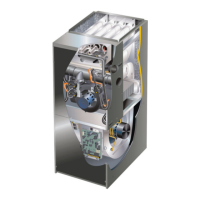
FIGURE 20
TYPICAL EXHAUST PIPE CONNECTIONS
HORIZONTAL DIRECT VENT APPLICATIONS
(Horizontal Right−Hand Air Discharge Application Shown)
2"
2"
2"
*2"
2−1/2",
3", OR
4"
DO NOT transition
from smaller to larger
pipe size in horizontal
runs of exhaust pipe.
TRANSITION
−36B−070
−36C−090
−60C−090
−60C−110*
−60D−135*
−36B−070
−36C−090
−60C−090
*2" maximum length
for −110 and −135
only.
Intake Piping
The G71MPP furnace may be installed only in direct vent
applications.
The G71MPP unit is designed for either left−side or right−
side air intake connections in either upflow or downflow ap-
plications. In horizontal applications, air intake must be
brought in through the top. Intake air piping is independent
of exhaust piping.