Page 29
the provided neutral terminals. See figure 44 for inte-
grated control configuration. This terminal is energized
in the heating mode when the combustion air inducer
is operating.
9 − One 24V H" terminal is provided on the furnace inte-
grated control terminal block. Any humidifier rated up
to 0.5 amp can be connected to this terminal with the
ground leg of the circuit being connected to either
ground or the C" terminal. See figure 44 for integrated
control configuration.
10 −Install the room thermostat according to the instruc-
tions provided with the thermostat. See table 10 for
thermostat connections. If the furnace is being
matched with a heat pump, refer to the instruction
packaged with the dual fuel thermostat.
NOTE − The discharge air temperature sensor is intended
to be mounted downstream of the heat exchanger and air
conditioning coil. It must be placed in free airflow, where
other accessories (humidifiers, UV lights etc.) will not inter-
fere with its accuracy. Wiring distance between the furnace
and discharge air sensor should not exceed 10 ft. when
wired with 18−gauge thermostat wire.
NOTE − Wiring distance between the furnace and the out-
door air sensor should not exceed 200ft. when wired with
18−gauge thermostat wire.
NOTE − Maximum total length of all connections on the
RSBus is limited to 1500ft
Thermostat Selection
The G71MPP is designed to operate in a variable rate ca-
pacity mode using a two−stage thermostat. The G71MPP
will automatically adjust firing rate based upon thermostat
cycle times.
The icomfort Touch thermostat must be used in commu-
nicating applications. Refer to the illustrations provided
with the thermostat for installation, set−up and operation.
For optimal performance in non−communicating applications,
Lennox recommends use of a high quality electronic digital ther-
mostat with adjustable settings for 1st stage / 2nd stage on / off
differentials and adjustable stage timers.
Lennox recommends the following two−stage thermostat
set−up for optimal variable rate capacity mode:
First heat stage differential set to 1/2 to 1 degree F; second
heat stage differential set to 1/2 or 1 degree F; second heat
stage upstage timer disabled, or set to maximum (1 hr mini-
mum).
Indoor Blower Speeds
1 − When the thermostat is set to FAN ON," the indoor
blower will run continuously at a percentage of the sec-
ond−stage cooling speed when there is no cooling or
heating demand. The percentage is set using DIP
switches 6 and 7.
2 − When the G71MPP is running in the heating mode, the
integrated control will automatically adjust the blower
speed to match the furnace firing rate. This speed can
be adjusted up or down by 7.5% or 15% using DIP
switches 14 through 16 for the low heat speed and 17
through 19 for the high heat speed.
3 − When there is a cooling demand, the indoor blower will
run on the cooling speed designated by the positions
of DIP switches 8 through 11.
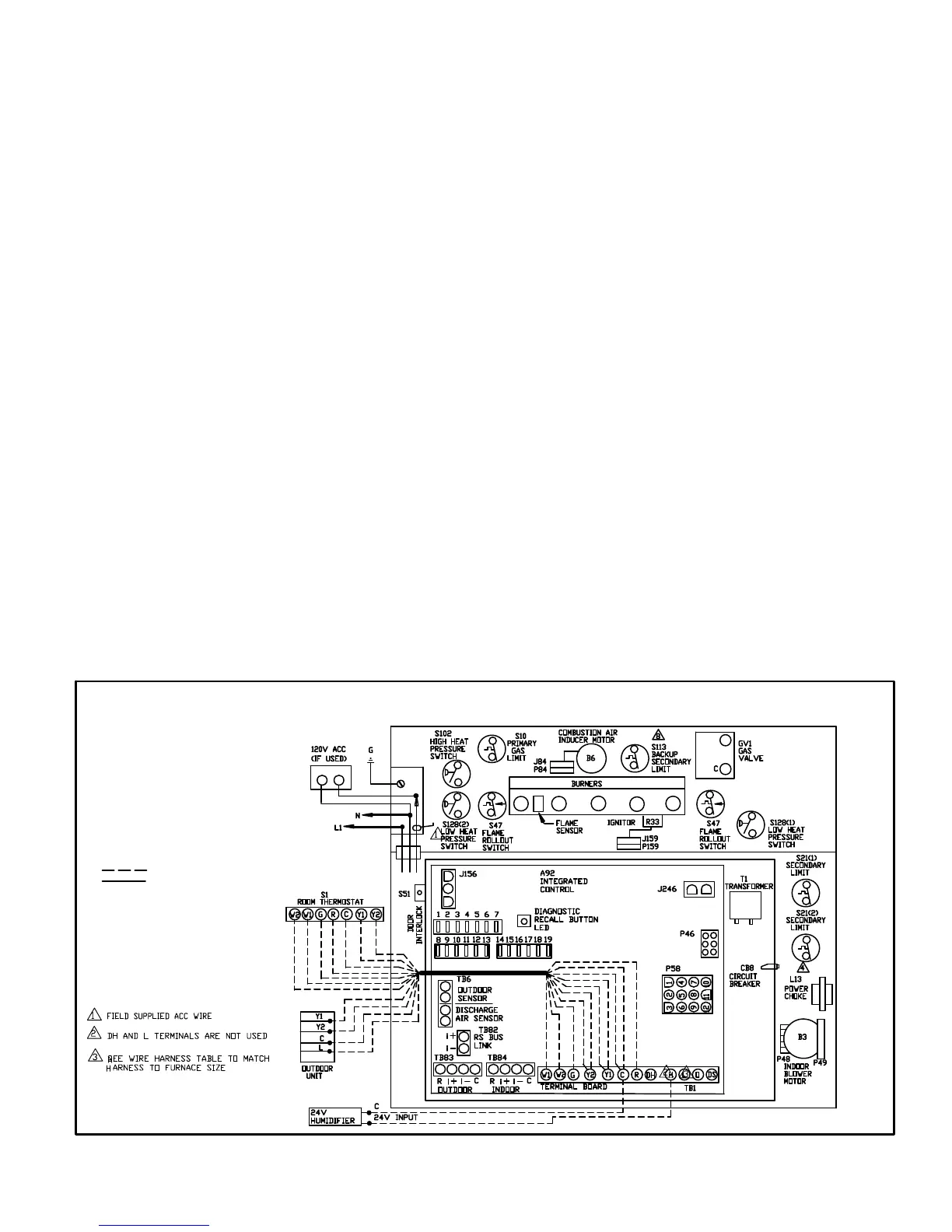
TYPICAL G71MPP FIELD WIRING DIAGRAM
FIGURE 40
FIELD INSTALLED CLASS II 24V
FIELD INSTALLED LINE VOLTAGE
USE COPPER CONDUCTORS ONLY.
 Loading...