Page 9
Setting an Upflow Unit
When the side return air inlets are used in an upflow ap-
plication, it may be necessary to install shims on the bottom
of the furnace. If desired, use field−supplied corrosion−re-
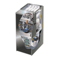
sistant 5/16 inch machine bolts (4) and nuts (8) to level the
furnace. See figure 8.
NOTE − The maximum length of the bolt is 1−1/2 inches.
1 − Lay the furnace on its back and drill a 5/16 inch diame-
ter hole in each corner of the furnace’s bottom. See fig-
ure 8 for the correct location of the holes. Drill through
the bottom panel and the bottom flange of the cabinet.
2 − Install one bolt and two nuts into each hole. Screw the
first nut onto a bolt and then insert the bolt into a hole. A
flat washer may be added between the nut and the bot-
tom of the unit.
3 − Screw another nut onto the bolt on the inside of the fur-
nace base. A flat washer may be added between the
nut and the bottom of the unit.
4 − Adjust the outside nut to the appropriate height and
tighten the inside nut to secure the arrangement.
FIGURE 8
1−3/4
(44)
1−3/4
(44)
3/8
(10)
1−3/4 (44)
3/8
(10)
3/8
(10)
3/8
(10)
1−3/4
(44)
Leveling Bolt Installation
Leveling Bolt
Locations
Leveling Bolt
Locations
Inches (mm)
Furnace Front
Furnace
Bottom
Downflow Applications
The unit may be installed three ways in downflow applica-
tions: on non−combustible flooring, on combustible flooring
using an additive base, or on a reverse−flow cooling coil
cabinet. Do not drag the unit across the floor in the
downflow position. Flange damage will result.
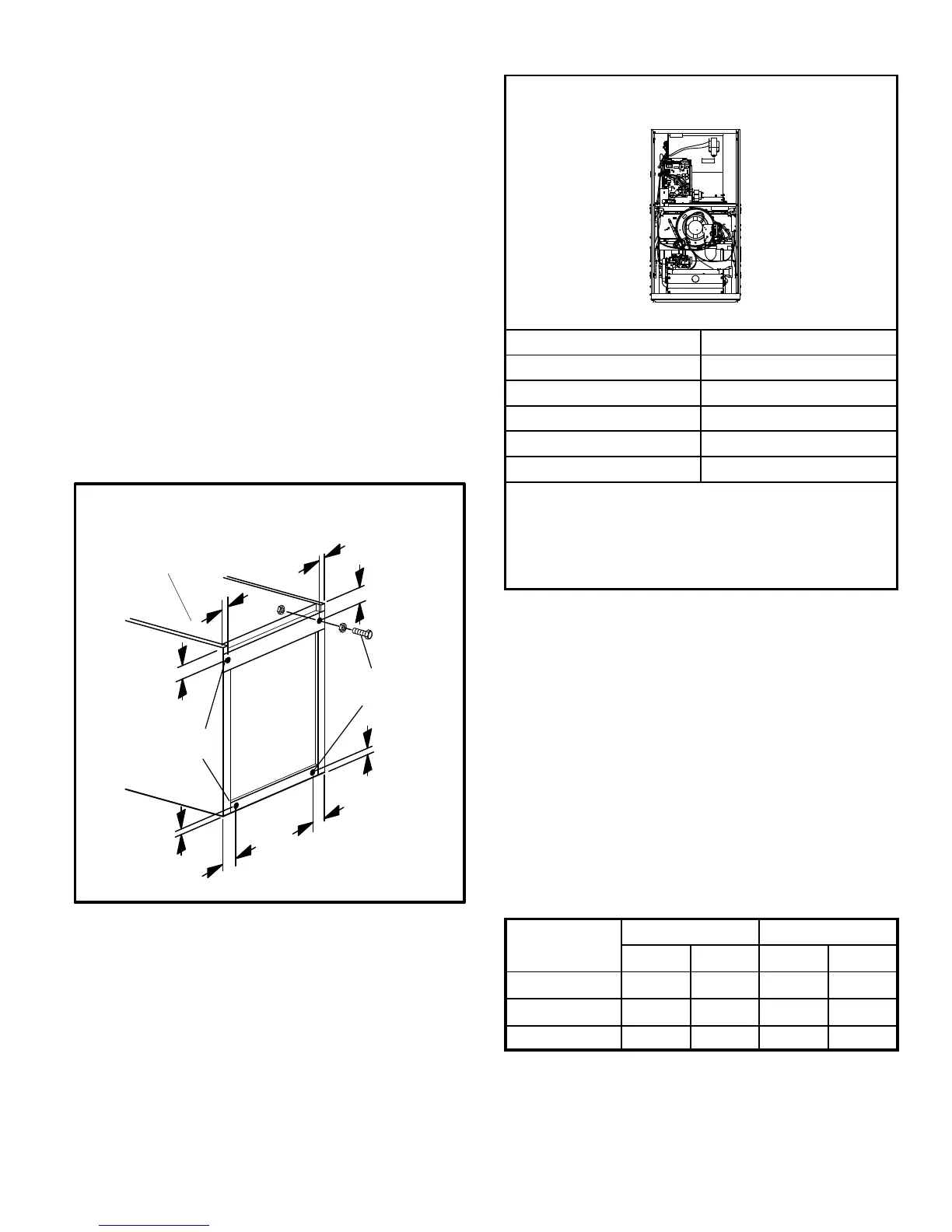
Refer to figure 9 for clearances in downflow applica-
tions.
Downflow Application Installation Clearances
Top
Bottom
Left Side
Right Side
Top 0
*Front 0
Back 0
Sides 0†
Vent 0
Floor NC‡
*Front clearance in alcove installation must be 24 in. (610 mm).
Maintain a minimum of 24 in. (610 mm) for front service access.
†Allow proper clearances to accommodate condensate trap and
vent pipe installation.
‡The furnace may be installed on a combustible wood floor if an op-
tional additive base is installed between the furnace and the com-
bustible floor.
FIGURE 9
Installation on Non−Combustible Flooring
1 − Cut floor opening keeping in mind clearances listed on
unit rating plate. Also keep in mind gas supply connec-
tions, electrical supply, flue and air intake connections
and sufficient installation and servicing clearances.
See table 1 for correct floor opening size.
2 − Flange warm air plenum and lower the plenum into the
opening.
3 − Set the unit over the plenum and seal the plenum to
the unit.
4 − Ensure that the seal is adequate.
TABLE 1
NON−COMBUSTIBLE FLOOR OPENING SIZE
Cabinet Width
Front to Rear Side to Side
in. mm in. mm
B Cabinet (17.5") 19 − 3/4 502 16 − 5/8 422
C Cabinet (21") 19 − 3/4 502 20−1/8 511
D Cabinet (24.5") 19 − 3/4 502 23 − 5/8 600
NOTE − Floor opening dimensions listed are 1/4 inch (6 mm) larger than
the unit opening. See dimension drawing on page 2.
 Loading...