@1999 Lennox Industries Inc.
Dallas, Texas, USA
GAS KITS AND ACCESSORIES
504,003M
10/99
Supersedes 3/99
GHR26 REPLACEMENT
COMBUSTION AIR BLOWER
INSTALLATION INSTRUCTIONS FOR REPLACEMENT COMBUSTION AIR BLOWER KIT
FOR USE ON GHR26 SERIES FURNACES
Package I of 1 contains the following:
1 - Combustion air blower assembly
1 - Replacement blower gasket
4 - Mounting screws
1- Turn offthe electrical power and the gas supply to the
unit.
2- Remove the lower access panel.
3- Disconnect the plugand jack in the widng harness that
supplies electrical power to the combustion air blower
assembly.
4- Loosen the hose clamp that holds the flue tee to the
combustion air blower.
5- Remove the four mounting screws that hold the
combustion air blower to the cold end header box.
Remove the combustion air blower.
6- Remove the old gasket from the cold end header box
and replace it with the new supplied gasket.
7- Install the new combustion air blower with the four
new mounting screws that are provided inthe kit. See
figure 1.
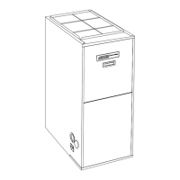
COLD END HEADER
REPLACEMENT
BLOWER
MOUNTING
BRACKET
FIGURE 1
8- Using the hose clamp, reconnect the combustion air
blower to the flue tee.
9- Reconnect the plug and jack in the wiring harness that
supplies the electrical power to the combustion air
blower assembly.
10- Reattach all hoses and tubes to collector box. See
figures 2, 3, and 4 for the proper tubing connections.
The tubingconnections will vary based on the direction
of the unit. Figures 5 and 6 illustrate the two types of
pressure switches that may be installed in the unit. See
figure 7 for the correct tubing connection ports on the
collector box.
11- Replace the lower access panel.
12- Restore the electrical power and the gas supply to the
furnace.
13- Refer to the furnace's installation instructions for the
start-up procedure.
DOWN FLOW AIR DISCHARGE*
Connecthose(greyround)To NEGATIVEsideon
pressureswitchand opentapon TOP of collectorbox.
AIR FLOW
Pressure
C_lector
Box
/
Connect red
squarehose to
POSITIVE side
on pressure
switch and open
tap on FRONT
of collector box.
*Tddelta pressure Switch
©
FIGURE 2
Page 1