OPTIONAL EQUIPMENT (Must Be Ordered Extra)
Master (Zone 1) Thermostat (Optional)
— Lennox recommends the use of a program-
mable thermostat for zone 1 master thermostat. See flowcharts on pages 4 and 5 for
recommended thermostats. Also see Thermostats bulletin in Accessories section.
Zone Thermostats (Optional)
— See flowcharts on pages 4 and 5 for recommended
zone thermostats. Also see Thermostats bulletin in Accessories section.
Round Zone Damper (Optional) — Round damper is constructed of heavy gauge gal-
vanized steel. Damper shell is furnished with one straight end and one crimped end
for ease of duct connection. Damper blade rotates smoothly in nylon bearings. Adjust-
able blade stop is furnished on damper blade for system balancing. Damper features
factory installed, heavy duty, synchronous motor with spring return open. Heavy duty
steel gearing provides long motor life. Damper springs open in case of power failure.
See damper specifications table for sizes, air resistance and shipping weights. Power
requirements: 24 VAC.
Rectangular Zone Damper (Optional)
— Rectangular damper is constructed of heavy
gauge aluminum and stainless steel. Damper is a slip-in, opposed blade type with duct
mounting plate on one end for ease of duct connection. Damper rotates smoothly in
nylon bearings. A rubber blade stop is furnished for installation on damper blade if
system balancing is required. Damper features factory installed, heavy duty, synchro-
nous motor with spring return open. Heavy duty steel gearing provides long motor life.
Damper springs open in case of power failure. See damper specifications table for
sizes, air resistance and shipping weights. Power requirements: 24 VAC.
Pressure Switch (Required for Heat Pump Operation)
— Pressure Switch (21J18) is re-
quired for proper system operation in heat pump applications.
Transformer (Optional)
— Transformer is required for operation of zone dampers. See
flowcharts on pages 4 and 5.
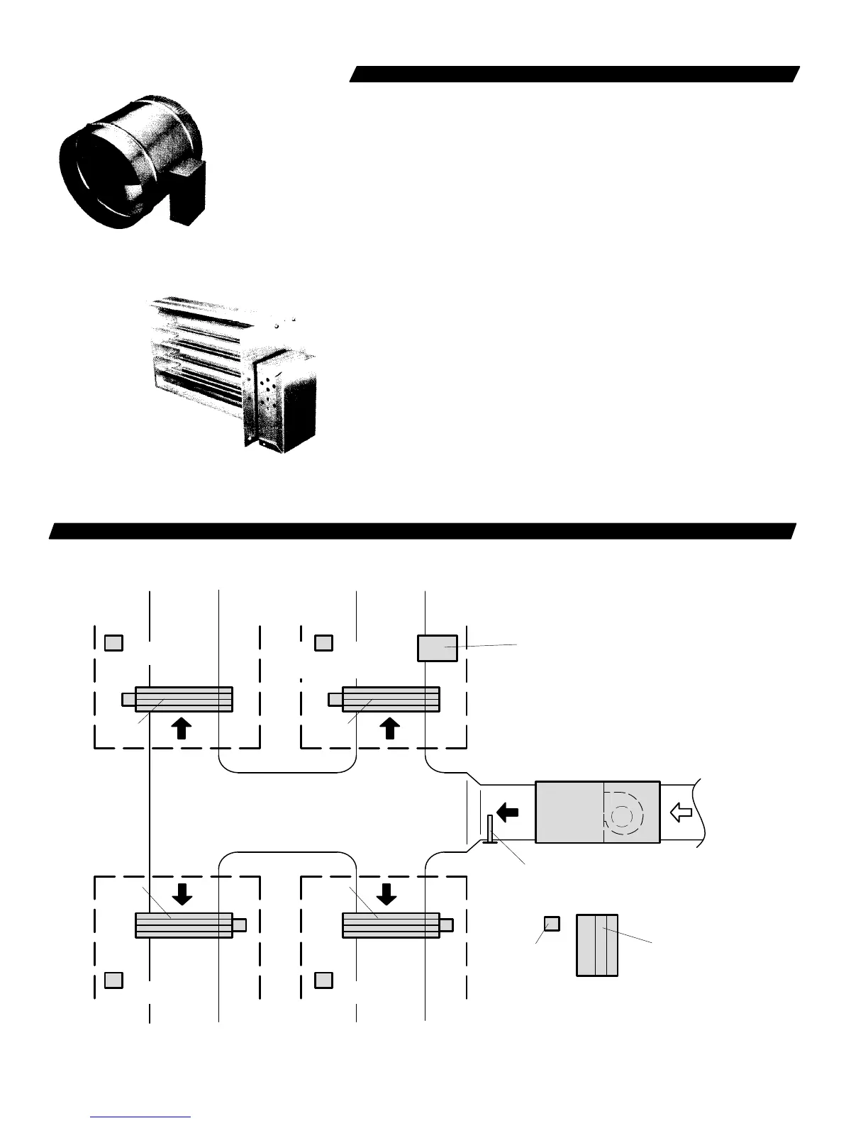
TYPICAL SYSTEM LAYOUT
ZONE 2 ZONE 1
ZONE 3 ZONE 4
ZONE 4
THERMOSTAT
ZONE 1
THERMOSTAT
(Master Thermostat)
ZONE 3
THERMOSTAT
ZONE 2
THERMOSTAT
HEATING/
COOLING
UNIT
HARMONY
CONTROL
CENTER
HARMONY
CONTROL
PANEL
SUPPLY
AIR
RETURN
AIR
ZONE
DAMPER
TRANSFORMER
ZONE
DAMPER
ZONE
DAMPER
ZONE
DAMPER
ZONE
DAMPER
DISCHARGE
AIR SENSOR
—
2
—
ROUND
ZONE DAMPER
RECTANGULAR
ZONE DAMPER

 Loading...
