1
Table of Contents
1. Safety Considerations ................................. 3
2. General Troubleshooting ............................ 4
2.1. Error Codes .......................................................4
2.2. Complaint Form .................................................5
2.3. Engineering Mode for System Query.................6
2.3.1. Engineering Mode Codes......................6
2.3.2. Engineering Mode Error Codes.............6
3. Quick Maintenance by Error Code ............. 7
4. Troubleshooting by Error Code .................. 8
4.1. TS01-IDU ........................................................... 8
4.2. TS01-ODU .........................................................8
4.3. TS02-S-INV .......................................................9
4.4. TS04-S-IDU .....................................................10
4.5. TS04-S-ODU ...................................................13
4.6. TS05-IDU ......................................................... 14
4.7. TS05-ODU .......................................................15
4.8. TS06-INV .........................................................16
4.9. TS07 ................................................................16
4.10. TS08-S .............................................................17
4.11. TS09-S .............................................................18
4.12. TS10-S .............................................................19
4.13. TS12-S .............................................................20
5. Check Procedures ..................................... 21
5.1. Temperature Sensor Check .............................21
5.2. Compressor Check ..........................................21
5.3. IPM Continuity Check ......................................23
5.4. Reversing Valve Check .................................... 24
6. Temperature Sensor Resistance Values .. 25
6.1. Temperature Sensor Resistance Values ..........25
6.2. Discharge Temperature Sensor Resistance
Values ..............................................................26
7. Pressure on Service Port .......................... 27
7.1. Cooling Chart (R-410A) ...................................27
7.2. Heating Chart (R-410A) ...................................28
7.3. R-410 System Pressure...................................29
8. Wiring Diagrams ........................................ 30
8.1. MWCB Indoor Units .........................................30
8.2. MCB Outdoor Units..........................................31
8.3. MWHB Indoor Units .........................................32
8.4. MHB Outdoor Unit ...........................................33
9. Indoor and Outdoor Unit Disassembly .... 35
9.1. MWCB and MWHB Unit Disassembly .............35
9.1.1. Front Panel Removal ..........................35
9.1.2. Control Board Removal ....................... 37
9.1.3. Evaporator Coil Removal ....................37
9.1.4. Fan Removal ....................................... 38
9.1.5. Step Motor Removal ...........................38
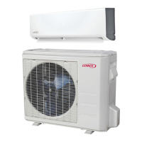
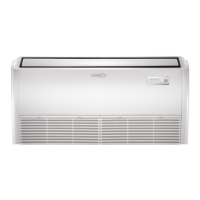
MCB / MHB Single-Zone
Outdoor Units
MWCB / MWHB Wall Mount Single-Zone
Indoor Unit
MINI-SPLIT SYSTEMS SERVICE MANUAL
MCB/MWCB and MHB/MWHB
Series Diagnostic Information
100042 5/2022
Please refer to 100041 for indoor and outdoor unit information.