Page 14
1
2
3
4
5
7
8
9
10
11
12
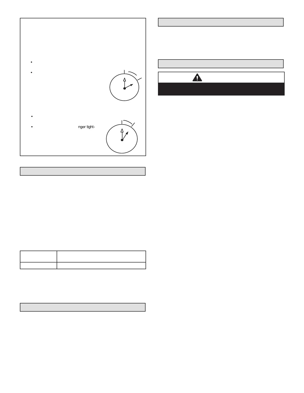
1/12 TURN
A service port cap protects the service port core from contamination
and serves as the primary leak seal.
1 -Remove service port cap with an appropriately sized wrench.
2 -Connect gauge set to service port.
3 - When testing is completed, replace service port cap and tighten
as follows:
With torque wrench, finger tighten and torque
cap per table 2.
Without torque wrench, finger tighten and
use an appropriately sized wrench to turn
an additional 1/6 turn clockwise.
1
2
3
4
5
6
7
8
9
10
11
12
1/6 TURN
Reinstall Stem Cap
Stem cap protects the valve stem from damage and serves as the
primary seal. Replace the stem cap and tighten as follows:
With torque wrench, finger tighten and
then torque cap per table 2.
Without torque wrench, fi
en and use an appropriately sized
wrench to turn an additional 1/12
turn clockwise.
FIGURE 17
Checking and Adding System Charge
The ML17XC1 unit is factory-charged with enough HFC-
410A refrigerant to accommodate a 15-foot length of re-
frigerant piping. For refrigerant piping greater than 15
feet, calculate the additional charge using the table below.
Then add the additional charge specied for the specic
indoor coil match-up listed on the unit charging sticker.
Charge should be checked and adjusted using the ta-
bles provided on the charging procedure sticker on
the unit access panel. Detailed information is given in
the ML17XC1 Installation and Service Procedures manu-
al, which is available on LennoxPros.com.
Refrigerant Charge per Line Set Length
LIQUID LINE DIA.
OUNCES PER 5 FEET (G PER 1.5 M) ADJUST
FROM 15 FEET (4.6 M) LINE SET*
3/8" (9.5 MM) 3 OUNCES PER 5' (85 G PER 1.5 M)
*If line length is greater than 15 ft. (4.6 m), add this amount. If line
length is less than 15 ft. (4.6 m), subtract this amount.
NOTE – Insulate liquid line when it is routed through areas where
the surrounding ambient temperature could become higher than the
temperature of the liquid line or when pressure drop is equal to or
greater than 20 psig.
High Pressure Switch (S4)
This unit is equipped with a high pressure switch which is
located on the liquid line. The SPST, normally closed pres-
sure switch opens when liquid line pressure rises above
the factory setting of 590 + 15 psig and automatically re-
sets at 418 + 15 psig.
Low Pressure Switch
This unit is equipped with a low pressure switch which is
located on the compressor suction line. The SPST, nor-
mally closed pressure switch opens when suction line
pressure drops below the factory setting of 40 ± 5 psig
and automatically resets at 95 ± 5 psig.
Homeowners Information
CAUTION
Before attempting to perform any service or maintenance,
turn the electrical power to unit OFF at disconnect switch.
In order to ensure peak performance, your system must
be properly maintained. Clogged lters and blocked air-
ow prevent your unit from operating at its most ecient
level. The system should be inspected and serviced be-
fore each cooling and heating season by a licensed pro-
fessional HVAC service technician (or equivalent).
Homeowner Maintenance
The following maintenance may be performed by the
homeowner.
• Contact a licensed professional HVAC technician to
schedule inspection and maintenance appointments for
your equipment before each heating and cooling season.
• Check the indoor unit lter each month and replace the
lter, if necessary.
• Have your Lennox dealer show you where your indoor
unit lter is located. It will be either at the indoor unit
(installed internal or external to the cabinet) or behind
a return air grille in the wall or ceiling. Check the lter
monthly and clean or replace it as needed. Disposable
lters should be replaced with a lter of the same type
and size.
• Check the indoor unit drain line for obstructions month-
ly. The indoor coil is equipped with a drain pan to collect
condensate formed as your system removes humidity
from the inside air. Have your dealer show you the loca-
tion of the drain line and how to check for obstructions.
(This would also apply to an auxiliary drain, if installed.)
• Check the area around the outdoor unit monthly and
remove any obstructions that may restrict airow to the
outdoor unit. This would include grass clippings, leaves,
or papers that may have settled around the unit.
• Trim shrubbery away from the unit and periodically
check for debris which collects around the unit.
• During the winter months, keep the snow level below
the louvered panels.
NOTE - The lter and all access panels must be in place
any time the unit is in operation. If you are unsure about
the lter required for your system, call your Lennox dealer
for assistance.
 Loading...