Page 19
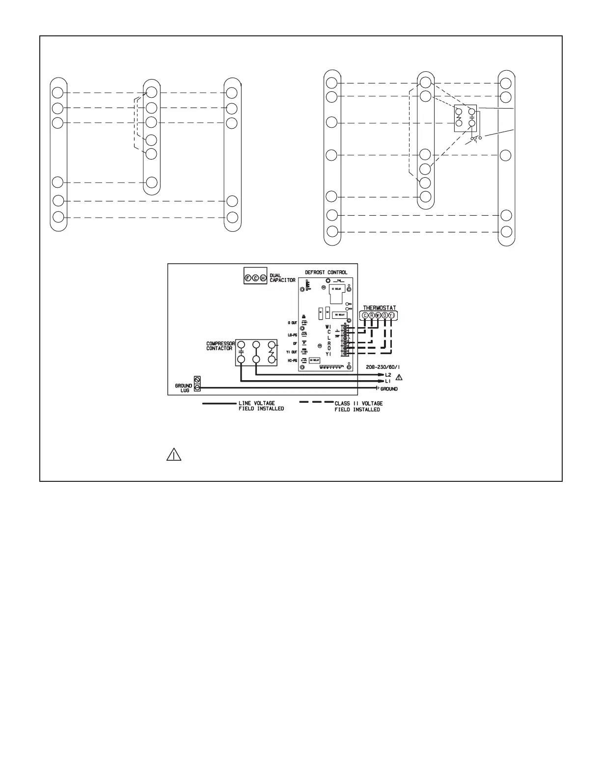
Typical 24VAC Control Wiring Diagrams (Field Installed)
THERMOSTAT INDOOR UNIT
R
C
W1
Y1
O
G
R
C
W1
W2
W3
G
R
C
W1
Y1
O
COMMON
1ST‐STAGE
AUXILIARY
HEAT
INDOOR BLOWER
COMPRESSOR
24V POWER
REVERSING VALVE
COMMON
1ST‐STAGE
AUXILIARY
HEAT
24V POWER
(SOME CONNECTIONS MAY NOT APPLY. REFER
TO SPECIFIC THERMOSTAT AND INDOOR UNIT. )
OUTDOOR UNIT
R
C
W1
Y1
O
G
R
C
W1
W2
W3
G
E
R
C
W1
Y1
O
EMERGENCY
HEAT
EMERGENCY
HEAT RELAY
OUTDOOR
THERMOSTAT
THERMOSTAT
INDOOR UNIT OUTDOOR UNIT
COMMON
1ST‐STAGE
AUXILIARY
HEAT
INDOOR BLOWER
COMPRESSOR
COMMON
1ST‐STAGE
AUXILIARY
HEAT
REWOP V42REWOP V42
(SOME CONNECTIONS MAY NOT APPLY. REFER TO
SPECIFIC THERMOSTAT AND INDOOR UNIT.)
REVERSING VALVE
WARNING! - ELECTRIC SHOCK HAZARD. Can cause INJURY
or DEATH. Unit must be grounded in accordance with national
and local codes.
NOTE - For use with copper conductors only. Refer to unit rating
plate for minimum circuit ampacity and maximum over‐current
protection size.
FIGURE 11. Typical Control Wiring
 Loading...