Page 55
Corp. 1244-L9
OUTDOOR CONTROLS
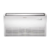
TYPICAL 9-12 KBTU OUTDOOR CONTROLS (208-230V)
FIGURE 68
1
216131214
5
6
10 7
89 11
4
3
15
1. Neutral
2. Power line input
3. Communications interface
4. Reactor interface 1
5. Reactor interface 2
6. Fan interface
7. Chassis electric heat
8. Compressor electric heat
9. Reversing valve interface
10. Reversing valve power
11. Heat tape wiring
12. Overload input
13. Heat packs
14. Compressor connections (U, V, and W)
15. Ground
16. Pressure switch input.
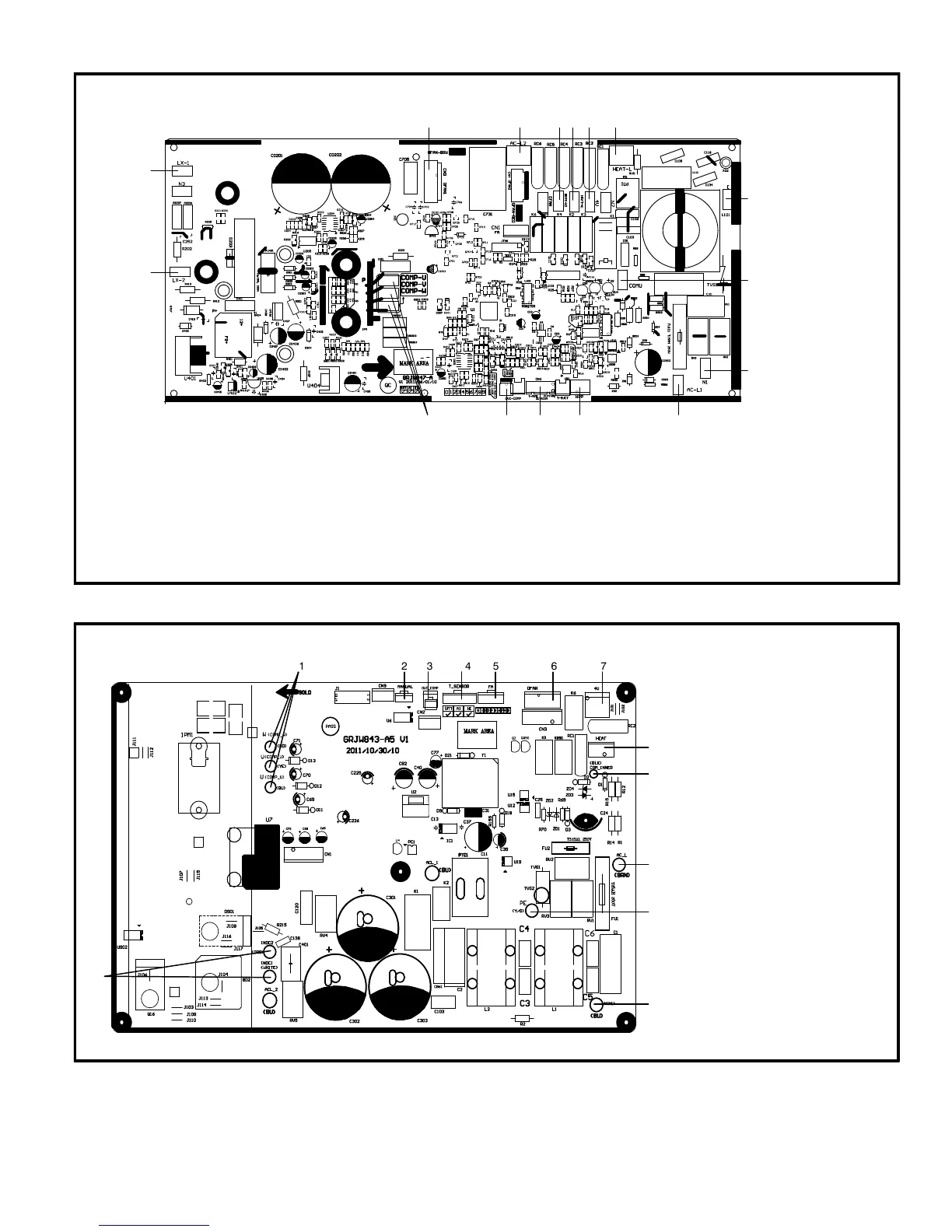
TYPICAL 18 - 24 KBTU OUTDOOR CONTROLS (208-230V)
FIGURE 69
1234567
8
9
10
11
12
13
1. Compressor interface
2. Outdoor coil temperature sensor in
put
3. Compressor overload protection ter
minal.
4. Outdoor temperature sensor
5. Electronic expansion valve terminal
6. Outdoor fan terminal
7. Reversing valve terminal
8. Chassis electric heat terminal
9. Communication input
10. Power line input
11. Ground wire
12. Neutral line
13. PFC inductor line
 Loading...