2
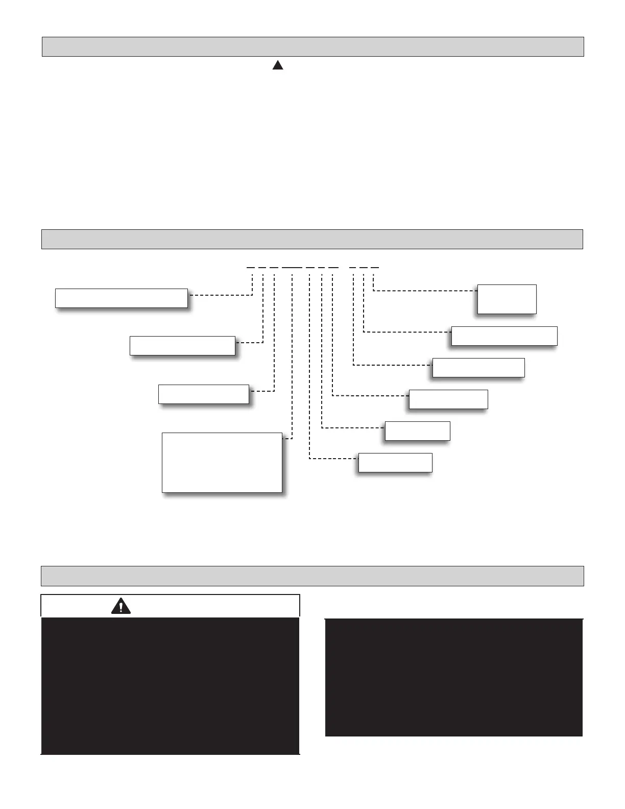
Model Number Identification
Safety Requirements
ELECTRICAL SHOCK, FIRE, OR EXPLOSION HAZARD.
Do not touch the unit or the controller if your hands are wet.
Do not operate appliances with an open ame near the unit.
Do not replace a fuse with a fuse of a dierent rating. Do not use a jumper wire to replace a fuse. Do not insert
your hands, tools or any other item into the air intake or air outlet at either the indoor or outdoor unit.
Do not allow children to operate the system.
This appliance is not intended for use by persons (including children) with reduced physical, sensory, or men-
tal capabilities, or lack of experience and knowledge, unless they have been given supervision or instruction
concerning use of the appliance by a person responsible for their safety.
Children should be supervised to ensure that they do not play with the appliance.
WARNING
!
System Piping
CAUTION
VRF system piping is customized for each installation.
The Lennox VRF Selection Software (LVSS) piping
report is an engineered design that must be followed.
The piping diagram or diagrams included within the LVSS
report have been prepared based on the information
provided to the Lennox VRF applications department.
When the indicated lengths change from the gures
stated within the report, it is imperative that prior to the
commencement of the refrigerant pipe work installation,
Lennox VRF applications department are informed of
these proposed changes.
Upon receipt of this new information the Lennox VRF
applications department will conrm any changes that
may be applicable to this installation. If changes are
required, a new piping diagram will be produced and will
supersede all other previously provided documents.
Failure to provide this information regarding changes
to the original design may lead to insucient capacity,
equipment failure, warranty being made void and the
refusal to commission the system.
NOTE - Lennox REAL/VRF and Lennox Mini-Split products are similar in appearance to each other. Refer to the unit’s
model number to determine if the unit is a REAL/VRF (V) or Mini-Split (M) unit. It is not possible to mix the two types of
equipment on any system.
V P C 036 H 4 M - 3 P S
Brand/Family
V = Variable Refrigerant Flow (VRF)
Unit Type
P = Heat Pump Outdoor Unit
Major Design Sequence
C = 3rd Generation
Cooling Eciency
H = High Eciency
Refrigerant Type
4 = R-410A
Voltage
P = 208/230V-1 phase-60hz
Nominal Cooling Capacity - Tons
018 = 1.5 tons
024 = 2 tons
036 = 3 tons
048 = 4 tons
060 = 5 tons
Refrigerant Circuits
M = Multiple Circuits
Minor Design Sequence
3 = Controls Protocol
No of Fans
S = Single Fan
D = Dual Fans
 Loading...