Page 6
NOTE — For proper voltages, select control wires gauge per table below.
WIRE RUN LENGTH AWG# INSULATION TYPE
LESS THAN 100' (30 METERS) 18 TEMPERATURE RATING
MORE THAN 100' (30 METERS) 16 35ºC MINIMUM.
NOTE — Wire tie provides low voltage wire strain relief and maintains
separation of field-installed low and high voltage circuits.
NOTE — Do not bundle any excess 24VAC control wires inside control box.
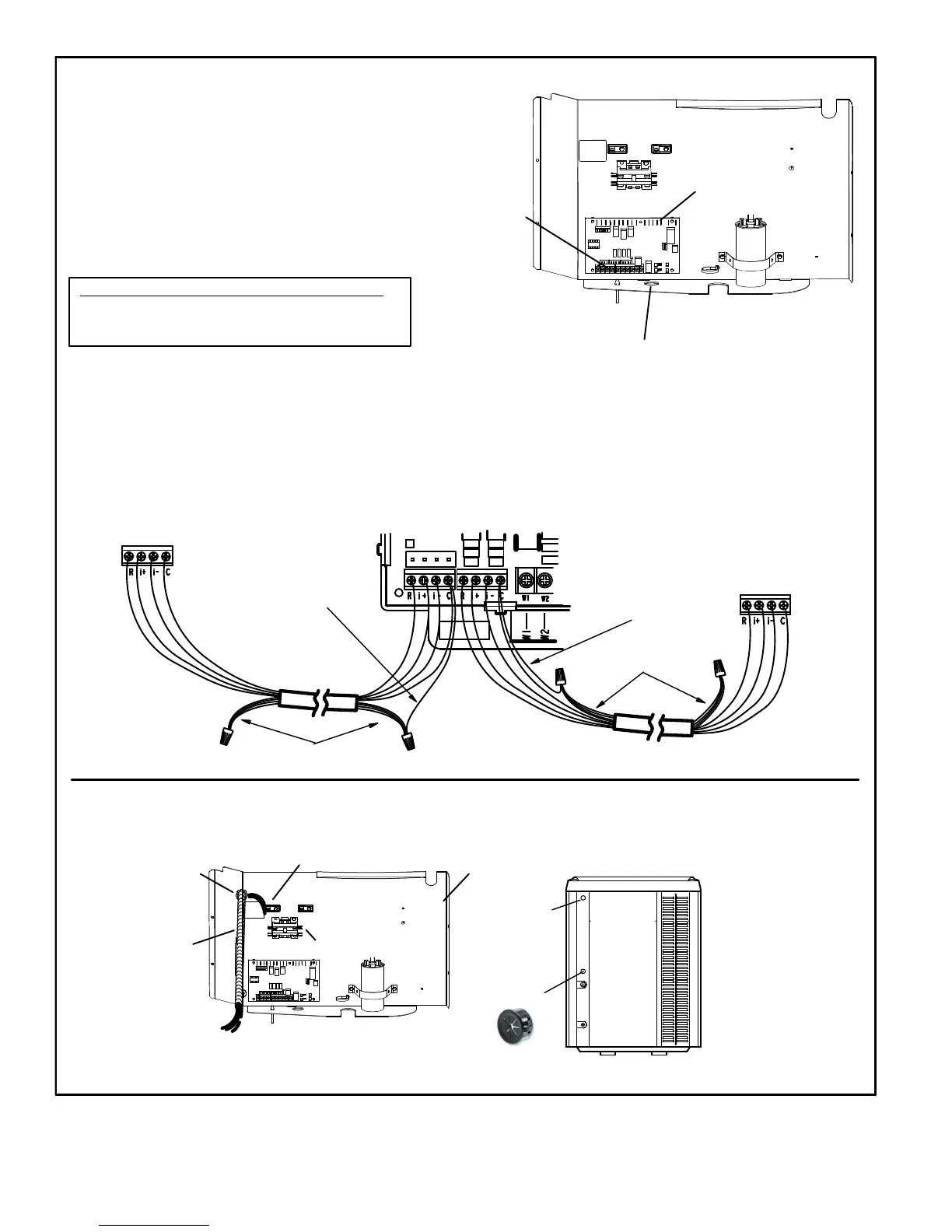
A. ROUTE CONTROL WIRES — NON-COMMUNICATING
CONTROL
(A175)
HOLE
Install low voltage control wiring from outdoor to indoor unit and from
thermostat to indoor unit. All low voltage wiring must enter unit through
provided field-installed busing installed in electrical inlet.
Run 24VAC control wires through hole with grommet.
Make 24VAC control wire connections to heat pump control (A175).
B. ROUTE CONTROL WIRES — COMMUNICATING
Maximum length of wiring (18 gauge) for all connections on the RSBus is 1500 feet (457 meters). Wires should be color-coded, with a temperature
rating of 95
º
F (35
º
C) minimum, and solid-core (Class II Rated Wiring). All low voltage wiring must enter unit through provided field-installed bushing
installed in electrical inlet.
Communicating systems using the iComfort
®
-enabled thermostat require four thermostat wires between the thermostat and the furnace/air han
dler control and four wires between the outdoor unit and the furnace/air handler control. When a thermostat cable with more than four wires is used,
the extra wires must be properly connected to avoid electrical noise (see illustration below).
Use a wire nut to bundle the four unused wires at each end of the cable. Each bundle should also include an additional wire that should be connected
on each end to the C terminal as shown in the figure below.
Any excess high voltage field wiring should be trimmed and secured away from any low voltage field wiring. To facilitate a conduit, a
cutout is located in the bottom of the control box. Connect conduit to the control box using a proper conduit fitting.
ROUTE HIGH VOLTAGE AND GROUND WIRES
CONTROL BOX
GROUND LUG*
CONTACTOR
WATERTIGHT
CONDUIT FITTING
WATERTIGHT
FLEXIBLE CONDUIT
TO SERVICE
DISCONNECT BOX
ACCESS VIEW
ELECTRICAL
INLET (HIGH
VOLTAGE)
WIRING ENTRY
POINTS
ELECTRICAL INLET (CONTROL WIRING —
LOW VOLTAGE). USE BUSHING
PROVIDED IN BAG ASSEMBLY HERE.
iComfort
®
-enabled
thermostat
iComfort
®
-enabled
Outdoor Unit
Single Wire To C
Terminal
Unused Wires
Unused Wires
* Attach field-provided
green ground wire to
provided ground lug.
NOTE - Grounding wire
must be a single, contin
uous wire run from unit
ground lug to earth
ground. DO NOT splice
wire.
A
B
Single Wire To C
Terminal
iComfort
®
-enabled
Indoor Unit
FIGURE 6
 Loading...