AIR TEMP.
q
F(
q
C)
LIQ. SUC. LIQ. SUC. LIQ. SUC. LIQ. SUC. LIQ. SUC. LIQ. SUC. LIQ. SUC. LIQ. SUC. LIQ. SUC.
65 (18.3) 145
71 155 65 160 65 168 63 176 62 162 68 157 69 153 66 159 64
75 (23.9) 167 77 181 70 188 70 197 68 203 66 185 72 182 72 180 71 188 68
RFCIV
85 (29.4) 192 81 208 75 216 74 227 73 233 70 210 73 204 73 210 74 219 72
95 (35.0) 221 84 238 80 247 78 258 77 266 74 252 76 244 76 245 77 253 75
105 (40.6) 253 87 270 84 280 82 292 80 299 77 287 79 278 79 279 79 287 76
65 (18.3) 140 79 159 73 164 71 173 71 179 68 157 71 158 70 142 73 151 69
75 (23.9) 161 80 183 75 189 73 199 73 205 70 187 73 182 72 168 75 179 71
TXV
85 (29.4) 189 81 209 77 217 75 228 75 235 72 217 74 205 73 202 76 211 73
95 (35.0) 220 83 238 80 247 78 258 77 266 74 255 76 246 76 245 77 249 74
105 (40.6) 254 84 269 82 279 80 292 79 299 77 289 77 280 79 280 78 286 75
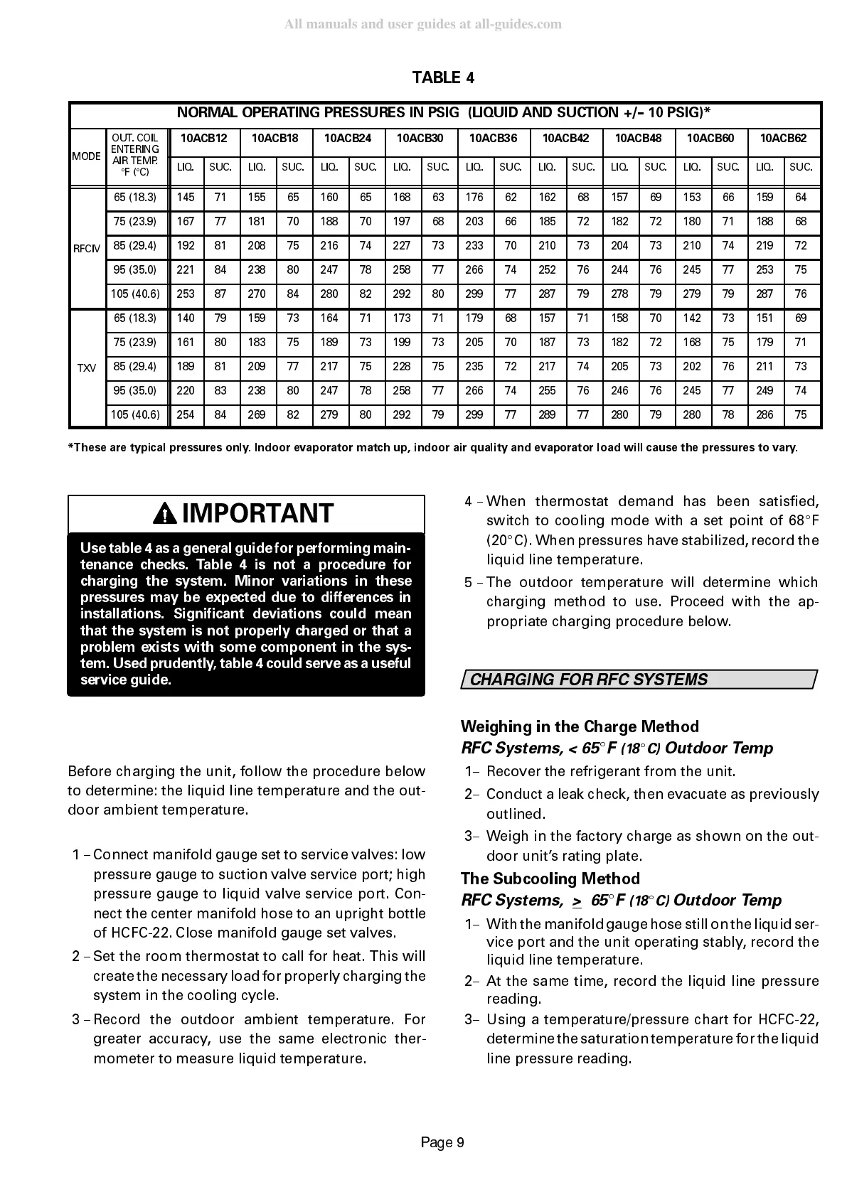
*These are typical pressures only. Indoor evaporator match up, indoor air quality and evaporator load will cause the pressures to vary.
IMPORTANT
Use table 4 as a general guide for performing main-
tenance checks. Table 4 is not a procedure for
charging the system. Minor variations in these
pressures may be expected due to differences in
installations. Significant deviations could mean
that the system is not properly charged or that a
problem exists with some component in the sys-
tem. Used prudently, table 4 could serve as a useful
service guide.
Before charging the unit, follow the procedure below
to determine: the liquid line temperature and the out-
door ambient temperature.
1 -- Connect manifold gauge set to service valves: low
pressure gauge to suction valve service port; high
pressure gauge to liquid valve service port. Con-
nect the center manifold hose to an upright bottle
of HCFC-22. Close manifold gauge set valves.
2 -- Set the room thermostat to call for heat. This will
create the necessary load for properly charging the
system in the cooling cycle.
3 -- Record the outdoor ambient temperature. For
greater accuracy, use the same electronic ther-
mometer to measure liquid temperature.
4 -- When thermostat demand has been satisfied,
switch to cooling mode with a set point of 68
E
F
(20
E
C). When pressures have stabilized, record the
liquid line temperature.
5 -- The outdoor temperature will determine which
charging method to use. Proceed with the ap-
propriate charging procedure below.
&+$5*,1* )25 5)& 6<67(06
Weighing in the Charge Method
RFC Systems, < 65
E
F
(18
E
C)
Outdoor Temp
1-- Recover the refrigerant from the unit.
2-- Conduct a leak check, then evacuate as previously
outlined.
3-- Weigh in the factory charge as shown on the out-
door units rating plate.
The Subcooling Method
RFC Systems, >
65
E
F
(18
E
C)
Outdoor Temp
1-- With themanifold gauge hose still on theliquid ser-
vice port and the unit operating stably, record the
liquid line temperature.
2-- At the same time, record the liquid line pressure
reading.
3-- Using a temperature/pressure chart for HCFC-22,
determinethe saturation temperature for the liquid
line pressure reading.
 Loading...