Quick Start
In the box
Server
Rail kit*
Cable management arm*
Material box, including items such as accessory kit, power cords*
and documentation
Note: Items marked with asterisk (*) are available on some models
only.
If any item is missing or damaged, contact your place of purchase.
Ensure that you retain your proof of purchase. They might be required
to receive warranty service.
First glance
Front view:
Note: Your server might look different from the following illustrations.
Figure 1. Server models with four 3.5-inch drive bays
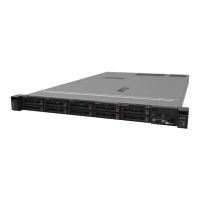
Figure 2. Server models with eight 2.5-inch drive bays
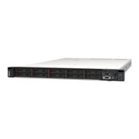
Figure 3. Server models with ten 2.5-inch drive bays
VGA connector (available
Pull-out information tab
XClarity Controller USB
USB 3.0 connector
Power button with power
Network activity LED
System ID button with ID
System error LED
Hot-swap drive bays
Drive status LED (yellow)
Drive activity LED (green)
Rear view:
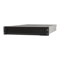
Figure 4. Server models with three PCIe slots
F
igure 5. Server models with two PCIe slots
F
igure 6. Server models with two hot-swap drive bays and one PCIe
slot
PCIe slot 1 on riser 1
assembly
PCIe slot 2 on riser 1
PCIe slot 3 on riser 2
Rear 2.5-inch drive bays
Power supply 1 Power supply 2 (available on
VGA connector XClarity Controller network
Ethernet connectors on the
LOM adapter (available on some
Note: For server models with two hot-swap drive bays in the rear, if the
server is installed in a rack and shipped to you, the server comes with
a shipping bracket installed. Before turning on the server, be sure to
remove the shipping bracket. For server models with two hot-swap
drive bays in the rear, if the server is installed in a rack for shipping, be
sure to install the shipping bracket. For details, refer to the
ThinkSystem SR630 Maintenance Manual, which is available at:
http://thinksystem.lenovofiles.com/help/topic/7X01/pdf_files.html