Elektrische Installation
Motoranschluss
4
23
MA 13.0001 DE-EN DE/EN 2.0
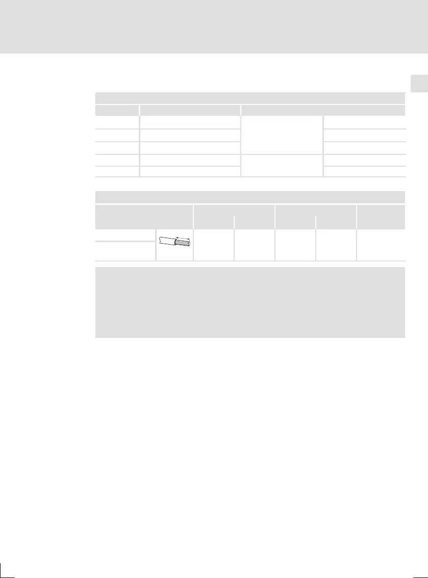
4.4 Motoranschluss
X3 Motoranschluss
Pin-Nr. Bezeichnung Spezifikation
1U
Motorphasen
Grundschwingung bei
Überlast für 2 s bis zu
32 A
eff
ca. 0 V ... 27 V
eff
2 V 0 V ... 13 A
eff
3 W 0 Hz ... 200 Hz
4 BR+
Bremse
24 V DC
5 BR- 0V
Klemmendaten
max. Leiterquerschnitt Anziehdrehmoment
Schrauben-
antrieb
Leitung [mm
2
] [AWG] [Nm] [lb-in]
flexibel
7mm
2,5 12 0,5 ... 0,6 4.4 ... 5.3
Schlitz
0,6 x 3,5
mit Aderend-
hülse
Stop!
Die Bremse wird über die Steuerspannung an X2 versorgt. Um den
störungsfreien Betrieb der Bremse zu gewährleisten, muss die
Steuerspannung im Toleranzbereich der verwendeten Bremse
liegen!
 Loading...